
Installation Instructions

5
HONEYWELL VR8215
CONVERSION INSTRUCTIONS
CAUTION
To prevenT unsaTisfacTory furnace operaTion, The proper
gas conversion kiT musT be used for The gas valve. use The
honeywell spring kiT only wiTh The honeywell gas valve.
NOTE: For low NOx models, see page 6 for NOx screens.
1. Turn off gas supply to the furnace.
2. Turn off the electrical power to the furnace.
3. Remove the furnace control access panel.
4. Separate the gas supply union and remove associated
downstream piping.
NOTE: Always use a backup wrench when removing or
replacing piping to avoid any undue strains or rotation of
controls.
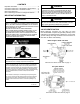
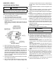
Honeywell VR8215
5. Remove the wires from the gas valve.
6. Remove the 4 sheet metal screws that fasten the manifold/
gas valve assembly to the burner box.
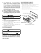
7. Visually inspect orices for damage and drill size (marked
on face with 1.25mm) before installation. Using the 7/16”
wrench, remove all existing natural gas orices and re-
place with the appropriate 1.25mm L.P. gas orices con-
tained in this kit. Tighten the orices to prevent gas leaks,
but do not overtighten. Retain the natural gas orices for
future reconversion.
8. Reinstall the manifold/gas valve assembly into the appli-
ance. Rewire the gas valve.
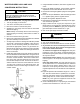
9. Remove both the inlet and outlet plugs on the gas valve,
using the 3/16” Allen wrench. Install the ttings which
accompany the manometers into the 1/8” taped holes of
the gas valve. Connect the manometers to the barbed
ttings.
10. Using a at blade screwdriver, remove the regulator cover
screw.
11. Using a at blade screwdriver, remove plastic regulator
adjustment screw located beneath the cover screw.
12. Remove the natural gas regulator spring from the regulator
sleeve.
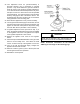
13. Insert the kit (P/N 0163M00078, Honeywell P/N 396221)
provided L.P. regulator spring into the regulator sleeve.
14. Replace the natural gas regulator adjustment screw with
the L.P. regulator adjustment screw included in the kit.
NOTE: The LP regulator should be adjusted near the bot-
tom of the adjustment range. DO NOT OVER-TIGHTEN.
15. Apply a liberal amount of pipe joint compound or pipe
thread tape to the threads and reassemble the piping
previously removed.
NOTE: the pipe joint compound or pipe thread tape must
be resistant to L.P. gas.
16. Turn on the gas supply and check for leaks.
WARNING
To avoid The possibiliTy of explosion or fire, never use a
maTch or open flame To TesT for leaks.
17. Turn on the electrical supply.
18. Adjust the room thermostat to allow for constant operation.
19. To check for air trapped in the supply line: Verify line
pressure is in the correct range. If manifold pressure is
indicated during the ignition trial, the valve is opening and
air may be in the line.
Units with hot surface ignitors: The valve will not open
until the ignitor is at the proper temperature (glowing
brightly).
Units with spark ignition: The valve will open as soon
as the spark starts. If no manifold pressure is indicated
during the trial for ignition, please return to step 13 to
ensure the correct spring was used and to ensure the
regulator adjustment is near the bottom of the adjustment
range.
20. If gas inlet pressure falls outside the range of 11” and 13”
W.C. after the unit has been in operation for 15 minutes,
adjust the gas supply pressure (not manifold pressure),
check piping size, etc., and/or consult with local utility.
NOTE: Any other gas-red equipment should be ON
before any adjustments are made.
21. Check manifold pressure. For propane gas, the manifold
pressure must be between 9.7” and 10.3” W.C.