
Installation Instructions

4
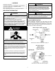
22. Turn adjustment screw out (counterclockwise) to
decrease pressure, turn in (clockwise) to increase
pressure. Only small variations in gas ow should be
made by means of the pressure regulator adjustment.
In no case should the nal manifold pressure vary more
than plus or minus 0.3” water column from the specied
nominal pressure. Any major changes in ow should be
made by changing the size of the burner orices. The
measured input rate to the furnace must not exceed the
rating specied on the unit rating plate.
23. Reset all other appliances so they function normally.
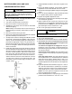
24. Turn off gas and electrical supply to the furnace, remove
the manometer hose from the pressure tap bosses, and
tighten the inlet and outlet pressure tap screws using
the 3/32” Allen wrench (clockwise 7 in-lb minimum).
25. If regulator adjustment screw (removed in step 11) is
white, the gasket supplied with the kit must be installed
on the regulator cover screw. The gasket is not required
if the regulator adjustment screw is black.
26. Replace the regulator cover screw on the regulator
sleeve.
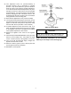
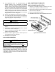
27. Attach the kit provided WARNING label to the gas valve
where it can be readily seen. Also attach the small
round L.P. label to the top of the regulator cover screw.
28. Turn on the gas and electrical supply, energize the
appliance and recheck for leaks.
29. Observe at least 3 ignition cycles to assure quick and
smooth ignition and burner operation.
30. Reinstall the access panels.
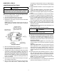
36G22 and 36J22 Model
CAUTION
To avoid The risk of properTy damage, personal injury
or fire, shuT off gas supply firsT, Then disconnecT The
elecTrical supply before proceeding wiTh conversion.
NOTE: Conversion instructions for the Honeywell
VR8215 gas valve begin on the following page.