
Conversion Kit Instructions

3
BEFORE BEGINNING CONVERSION:
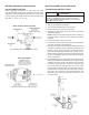
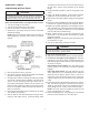
VALVE IDENTIFICATION
Before beginning conversion, the type valve you have
must be identifi ed. Compare the gas valve presently on the
equipment to the drawing below to identify the correct valve
you are working with. Page numbers for the instructions for
that valve are below each drawing.
White-Rodgers 36G22 and 36J22
See following Instructions for these valves.
Honeywell VR8215
Instructions for this valve start on page 5.
WHITE-RODGERS 36G22 AND 36J22
CONVERSION INSTRUCTIONS
CAUTION
TO PREVENT UNSATISFACTORY FURNACE OPERATION, THE
PROPER GAS CONVERSION KIT MUST BE USED FOR THE GAS
VALVE. USE THE WHITE-RODGERS SPRING KIT ONLY WITH THE
WHITE-RODGERS GAS VALVES.
NOTE: For low NOx models, see page 6 for NOx screens.
1. Turn off gas supply to the furnace.
2. Turn off the electrical power to the furnace.
3. Remove the furnace control access panel.
4. Separate the gas supply union and remove associated
downstream piping.
NOTE: Always use a backup wrench when removing or
replacing piping to avoid any undue strains or rotation of
controls.
5. Remove the wires from the gas valve.
6. Remove the 4 sheet metal screws that fasten the manifold/
gas valve assembly to the burner box.
7. Visually inspect orifi ces for damage and drill size (marked
on face with 1.25mm) before installation. Using the 7/16”
wrench, remove all existing natural gas orifi ces and re-
place with the appropriate 1.25mm L.P. gas orifi ces con-
tained in this kit. Tighten the orifi ces to prevent gas leaks,
but do not overtighten. Retain the natural gas orifi ces for
future reconversion.
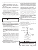
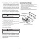
8. Install water manometer using Valve Pressure Check Kit
P/N 0151K00000S included with this kit. Using the includ-
ed 3/32” hex wrench, rotate outlet pressure tap screw one
revolution counterclockwise. Attach the included 5/16”
hose to the inlet and outlet pressure boss of the valve.
Hose should overlap boss 3/8”. Connect 5/16” side of in-
cluded connector to the hose on the outlet boss. Connect
1/4” side of the connector to the manometer hose. The
manometer must have a scale range of at least 0” to 20”
of water column.