
Propane Conversion Kit Instructions

5
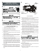
HONEYWELL VR9205Q
CONVERSION INSTRUCTIONS
NOTE: For low NOx models,
see table of contents for NOx Screen section.
1. Turn off the gas supply to the furnace.
2. Turn off the electrical power to the furnace.
3. Remove the furnace control access panel.
4. Check for the presence of NOx screen and remove per
NOx instruction.
5. Separate the gas supply union and remove associated
downstream piping.
6. Always use a backup wrench when removing or replacing
piping to avoid any undue strains or rotation of controls.
7. Remove the wires from the gas valve.
8. Remove the 4 shee t metal screws that fasten the mani-
fold/gas valve assembly to the burner box.
9. Visually inspect orifices for damage and drill size (marked
on face with 55) before installation. Using the 7/16" wrench,
remove all existing natural gas orifices and replace with
the appropriate marked 55 L.P. gas orifices contained in
this kit. Tighten the orifices to prevent gas leaks, but do
not overtighten. Retain the natural gas orifices for future
reconversion.
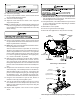
10. Remove both the inlet and outlet plugs on the gas valve,
using the 3/16” allen wrench. Install the fittings, which
accompany the manometers, into the 1/8” NPT holes of
the gas valve. Connect the manometers to the barbed fit-
tings.
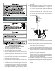
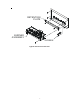
Gas Valve
On/Off
Selector Switch
Regulator
Vent
High
Regulator
Adjust
Low
Regulator
Adjust
Honeywell VR9205Q
11. Remove both regulator cover screws and retain with the
Natural Gas orifices for future reconversion.
12. Using a T-25 Torx driver (L Torx tool included in kit) or 3/
16" flat head screwdriver, remove both regulator adjust-
ment screws.
13. Remove both silver colored Natural Gas regulator springs
from the regulator sleeves and retain with the Natural Gas
orifices for future reconversion.
14. Insert the L.P. regulator springs (provided in the conver-
sion kit and color-coded red) into the regulator sleeves.
15. Replace the High regulator adjustment screw and adjust it
clockwise to bottom stop. Follow instructions below be-
ginning in step 26 for checking & adjustment to verify mani-
fold pressure falls into the desired range.
16. Replace the Low regulator adjustment screw and adjust it
clockwise to bottom stop. Follow instructions below be-
ginning in step 25 for checking & adjustment to verify mani-
fold pressure falls into the desired range
17. Reinstall the manifold/gas valve assembly into the appli-
ance. Rewire the gas valve.
18. Apply a liberal amount of pipe joint compound or pipe thread
tape to the threads and reassemble the piping previously
removed. Note: the pipe joint compound must be resistant
to L.P. gas.
19. Turn on the gas supply.
20. Using a soap and water solution, check for leaks around
the gas valve/manifold connection.
21. Turn on the electrical supply.
22. Adjust the room thermostat to obtain a first stage (W1
only) burner operation.