
Propane Conversion Kit Instructions

4
19. Turn on the gas supply.
20. Using a soap and water solution, check for leaks around
the gas valve/manifold connection.
21. Turn on the electrical supply.
22. Adjust the room thermostat to obtain a first stage (W1
only) burner operation.
NOTE: For hybrid models, the control board dip switches need
to be set to 2 stg position to set and verify first stage heat.
(See installation instructions supplied with the unit for dip
switch settings.)
23. Using a soap and water solution, check for leaks around
the gas valve/manifold connection and the burner orifices.
Repair any leaks before continuing.
24. NOTE: Any other gas-fired equipment should be ON be-
fore any adjustments are made.
After the furnace has been in operation for 15 minutes,
adjust the gas supply pressure (not manifold pressure) to
obtain a range between 11” and 13” W.C. If the gas inlet
pressure falls outside of this range, then make necessary
L.P. service regulator(s) adjustments; check piping size,
etc., and /or consult with L.P. provider.
25. With the furnace operating in its low-fire (W1) condition,
the manifold pressure should be 6” W.C. ± 0.30”. If neces-
sary, this pressure can be adjusted using the gas valve
low regulator adjustment screw. Turn clockwise to increase
pressure and counterclockwise to decrease manifold pres-
sure.
26. Readjust the room thermostat to obtain a second stage
call for heat (W2). The manifold pressure for the W2 con-
dition should be 10” W.C. ± 0.30” W.C. If necessary, this
pressure can be adjusted using the gas valve high regula-
tor adjustment screw. Turn clockwise to increase pres-
sure and counterclockwise to decrease manifold pressure.
27. Using the room thermostat to cycle the unit, observe a
minimum of three (3) smooth ignition cycles.
28. Turn off gas and electrical supply to the furnace, remove
the manometer hose from the pressure tap bosses, and
tighten the inlet and outlet pressure tap screws using the
3/32” Allen wrench.
29. Replace both regulator cover screws on the regulator
sleeve.
30. IMPORTANT NOTE: Apply the conversion label (B14933-
151) provided with the conversion kit. This label must be
attached adjacent to the rating plate.
31. For hybrid models, control board switches may need to be
re-set to single stage operation depending on installers
preference of operation.
32. Reinstall the access panels.
33. Turn on the gas and electrical supply.
34. Reset all other appliances so they function normally.
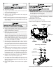
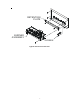
Inlet
Pressure Boss
Low
Regulator Adjust
High Regulator
Adjust
Regulator
Vent
Outlet
Pressure Boss
White-Rodgers 36G54/36J54
Regulator
Cover Screw
Regulator Spring
Plastic Regulator
A
djustment Screw
High
Low
White-Rodgers 36G54/36J54 Springs and Regulator Screws