
Installation Instructions

5
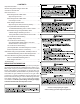
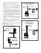
6. Install pressure switch in bushing. Pressure switch will be
installed outside of the wrapper (see Figure 6.)
NOTE: Ensure that the switch is upright in all applica-
tions.
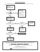
7. Perform installation check out procedure (piping leak check,
line pressure measurement, manifold pressure adjustment,
etc.) as outlined in the unit installation instructions.
8. Turn OFF gas supply.
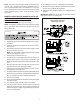
9. Turn OFF power to furnace. Connect jumper harness be-
tween LPLP switch and gas valve and gas valve wiring as
indicated in Figure 7 (single-stage models - some models
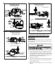
may require the use of long single-stage harness) or Fig-
ures 8-11 (two-stage models). Some two-stage models may
require the use of long jumper wires to accommodate con-
nection of the switch. (2nd long jumper wire can be taken
from long single stage harness.)
NOTE: Do not run wires through the gas pipe opening if
gas piping is present. Pipe could easily cause damage to
the wires.
10. Turn ON power to furnace. Verify proper unit operation.
11. Remove backing from kit label. Fold label around jumper
harness wire to indicate kit installation.
12. Adhere kit wiring diagram adjacent to existing unit wiring
diagram.
IMPORTANT NOTE: Secure all wires to avoid their contact
with any hot surfaces or moving parts.
Honeywell VR82 or Valves
Used on 80% Models
V 9205QR
Fi
g
ure 6
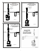
LP Low
Pressure
Switch
Gas Valve
Single-Stage
Jumper Harness
Gas Valve Wiring
from
Furnace Wiring
Harness
Kit
Label
Brown or Gray Wire
Honeywell or White-Rodgers Gas Valves
LP Low Pressure Switch Wiring
Single-Stage Models
White-Rodgers Valve Shown
Figure 7
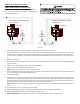
LP Low
Pressure
Switch
Kit
Label
Gas Valve
Two-Stage
Jumper Harness
Gas Valve Wiring
from
Furnace Wiring
Harness
White-Rodgers Gas Valve
&
Wiring Harness Connection
LP Low Pressure Switch Wiring
Two-Stage Models
Figure 8