
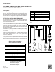
Installation Instructions

3
NOTE: To ensure proper operation, install, operate and main-
tain the unit in accordance with these installation instruc-
tions, all local building codes and ordinances. In their ab-
sence, follow the latest edition of the National Fuel Gas Code
(NFPA 54/ANSI Z223.1), and/or CAN/CSA B149.1 Installa-
tion Codes.
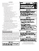
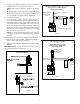
MODELS USING WHITE-RODGERS 36F & 36E
GAS VALVES WITH 1/8” NPT INLET
PRESSURE PORT
(Alternate method on page 4 may also be used.)
NOTE: All threaded connections must be sealed with Teflon
tape or pipe dope. Pipe sealant must be approved for use
with propane gas.
1. Remove plug from the gas valve inlet pressure tap port.
Save plug.
2. Install the supplied close nipple into the open inlet pres-
sure tap port.
3. Thread the provided tee onto free end of the nipple. Orient
the tee as shown in figure(s).
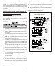
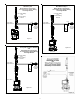
NOTE: On some models, tee orientation depends on which
side the gas supply line enters.
4. Install pressure switch into the tee.
5. Temporarily fit a field-supplied pressure tap into the re-
maining leg of the tee. This pressure tap will allow gas
supply line pressure measurement during installation check
out.
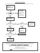
6. Attach the pressure tap to a manometer or pressure mea-
surement device before opening gas supply.
7. With gas valve and manifold installed in the unit, connect
gas supply line to the gas valve.
8. Perform installation check out procedure (piping leak check,
line pressure measurement, manifold pressure adjustment,
etc.) as outlined in the unit installation instructions.
9. Turn OFF gas supply.
10. Remove field-supplied pressure tap from tee and insert plug
removed in step 1.
11. Turn ON gas supply and leak check inserted plug.
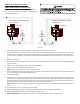
12. Turn OFF power to furnace. Connect jumper harness be-
tween LPLP switch and gas valve and gas valve wiring as
indicated in Figure 7 (single-stage models) or Figures 6, 8
or 9 (two-stage models).
13. Turn ON power to furnace. Verify proper unit operation.
14. Remove backing from kit label. Fold label around jumper
harness wire to indicate kit installation.
15. Adhere kit wiring diagram adjacent to existing unit wiring
diagram.
IMPORTANT NOTE: Secure all wires to avoid their contact
with any hot surfaces or moving parts.
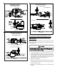
White-Rodgers 36F Valve
White-Rodgers 36E Valve
Right Facing Gas Inlet
Figure 2