
LPKMOD Installation Instructions

4
time during a heating cycle, at which time the display will
show “Ft”. While the display is showing “Ft”, pressing and
holding the Fault Recall Push-Button for 3 seconds will
enable the field test mode and override the normal firing
rate sequence at a rate of 100% for 5 minutes or until the
end of the call for heat. The display will show the normal
“Hi” while the control is firing at 100%. If the Fault Recall
Push-Button has not been pressed within 5 seconds of
displaying “Ft” the display will revert back to normal.
18. Measure furnace gas supply pressure with burners firing.
Supply pressure must be within the range specified in the
Inlet Gas Supply Pressure table.
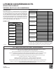
Natural Gas
Minimum: 5.0" w.c. Maximum:10.0" w.c.
Propane Gas
Minimum: 11.0" w.c. Maximum:13.0" w.c.
Inlet Gas Supply Pressure
If supply pressure differs from table, make the necessary ad-
justments to pressure regulator, gas piping size, etc., and/or
consult with local gas utility.
19. Using a soap and water solution, check for leaks around
the gas valve/manifold connection and the burner orifices.
Repair any leaks before continuing.
20. Turn OFF all electrical power to the system.
21. Turn OFF gas to furnace at the manual gas shutoff valve
external to the furnace, disconnect manometer and rein-
stall plug.
GAS MANIFOLD PRESSURE ADJUSTMENT
The manifold pressure must be measured with the burners
operating. To measure the manifold pressure, use the follow-
ing procedure.
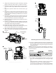
22. Outlet pressure tap connections: Remove the outlet
pressure boss plug. Install an 1/8" NPT hose barb fitting
into the outlet pressure tap.
23. Attach a hose and manometer to the outlet pressure barb
fitting.
24. Turn ON the gas supply.
25. Turn on power and close thermostat “R” and “W1” con-
tacts to provide a call for low stage heat.
NOTE: After every time the main power is turned off and
back on, the furnace will enter a calibration routine on the
next call for heat The inducer will ramp up and down during
the calibration routine. After calibration, the furnace will
proceed to ignition cycle.
26. Field Test Mode is intended to help a service person
troubleshoot and check out an installed appliance.
To enter Field Test Mode the Fault Recall Push-Button
must be pressed twice within a 5 second period at any
time during a heating cycle, at which time the display will
show “Ft”. While the display is showing “Ft”, pressing and
holding the Fault Recall Push-Button for 3 seconds will
enable the field test mode and override the normal firing
rate sequence at a rate of 100% for 5 minutes or until the
end of the call for heat. The display will show the normal
“Hi” while the control is firing at 100%. If the Fault Recall
Push-Button has not been pressed within 5 seconds of
displaying “Ft” the display will revert back to normal.
NOTE: Gas valve is factory set and does NOT require any
field adjustment. Do NOT attempt to adjust valve.
Measure the gas manifold pressure with burners firing.
27. Turn off all electrical power and gas supply to the system.
28. Remove the manometer hose from the hose barb fitting.
29. Remove the 1/8" NPT hose barb fitting from the outlet
pressure tap. Replace the outlet pressure boss plug and
seal with a high quality thread sealer.
30. Turn on electrical power and gas supply to the system.
31. Close thermostat contacts “R” and “W1/W2” to energize
the valve.
Using a leak detection solution or soap suds, check for leaks at
outlet pressure boss plug. Bubbles forming indicate a leak. SHUT
OFF GAS AND REPAIR ALL LEAKS IMMEDIATELY!
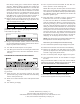
Range Nominal
Natural High Stage 3.2 - 3.8" w.c. 3.5" w.c.
Propane High Stage 9.5 - 10.5" w.c. 10.0" w.c.
Manifold Gas Pressure
Gas
32. If no leak is detected, reinstall the access panels.
33. Reset all other appliances so they function normally.
Goodman Manufacturing Company, L.P.
5151 San Felipe, Suite 500, Houston, TX 77056
www.daikincomfort.com, www.goodmanmfg.com and www.amana-hac.com
© 2011, 2013 Goodman Manufacturing Company, L.P.