
LPKMOD Installation Instructions

3
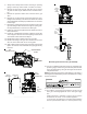
5. Always use a backup wrench when removing or replacing
piping to avoid any undue strains or rotation of controls.
6. Remove the wires from the gas valve. Be sure to remove
any wire ties that may be attached to the manifold assem-
bly.
7. Remove the pressure switch hose connected to the gas
valve.
8. Remove the 4 sheet metal screws that fasten the mani-
fold/gas valve assembly to the burner box. Retain the natural
gas manifold/valve assembly for possible future reconversion
to natural gas.
9. Remove the natural gas burners from the burner rack by lift-
ing and rotating to allow clearance through the opening. Re-
tain for possible future reconversion to natural gas.
10. Install L.P. gas burners supplied in the kit. Rotate and set on
tabs in burner box.
11. Install L.P. manifold/valve assembly supplied in the kit. Be
sure to align the orifices in the burner opening. Fasten with 4
sheet metal screws retained from Step 8.
12. Reattach the pressure switch hose to the gas valve.
13. Reattach the wiring to the gas valve and wire tie any loose
wires to avoid contact with hot or moving parts.
14. Apply a liberal amount of pipe joint compound or pipe thread
tape to the threads and reassemble the piping previously
removed.
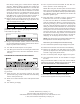
ATMOSPHERE
PORT
DIRECTION
FLOW
PS
CONNECTION
Inlet
Pressure
Tap
1/8 NPT
2-PIN
POWER
CONNECTOR
i
M
a
n
o
m
e
t
e
r
M
a
n
o
m
e
t
e
r
H
o
s
e
O
p
e
n
t
o
A
t
m
o
s
p
h
e
r
e
__________________________
Outlet
Pressure
Tap
1/8 NPT
__________________________
Gas Line
Gas
Shutoff
Valve
Gas Line
To Furnace
Drip Leg Cap
With Fitting
Manometer Hose
Measuring Inlet Gas Pressure (Alt. Method)
15. Connect a calibrated water manometer (or appropriate gas
pressure gauge) at either the gas valve inlet pressure boss
or the gas piping drip leg. See gas valve figure for location of
inlet pressure boss.
NOTE: If measuring gas pressure at the drip leg or gas valve, a
field-supplied hose barb fitting must be installed prior to making
the hose connection.
16. Turn on the electrical supply.
17. Turn ON the gas supply and operate the furnace and all
other gas consuming appliances on the same gas supply
line.
Field Test Mode is intended to help a service person
troubleshoot and check out an installed appliance.
To enter Field Test Mode the Fault Recall Push-Button
must be pressed twice within a 5 second period at any-