
Kit Installation Manual

4
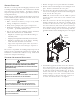
For three phase applications with circuit breaker,
cut the circuit breaker cover along the dotted lines,
as shown in Figure 6.
E
LECTRICAL
C
ONNECTIONS
HIGH VOLTAGE !
D
ISCONNECT
ALL
POWER
BEFORE
SERVICING
.
M
ULTIPLE
POWER
SOURCES
MAY
BE
PRESENT
. F
AILURE
TO
DO
SO
MAY
CAUSE
PROPERTY
DAMAGE
,
PERSONAL
INJURY
OR
DEATH
.
WARNING
1. All electric heat kits have lugs for connection of high
voltage power supply. Insert the power leads into the
lugs (either on the terminal block or circuit breaker)
and tighten. The power must be routed through a strain
relief as they enter the cabinet. For two power supply
electric heat kits (all circuit breaker connections), be
sure to connect the correct power supply to the correct
circuit breaker – check the air handler rating plate for
Minimum Circuit Ampacity and Maximum Overcurrent
Protection electrical ratings of each circuit.
2. Connect the ground wire from the power supply to the
ground lug provided in the air handler. For two power
supply electric heat kits, one ground lug is provided
with the air handler and the second ground lug is supplied
with the electric heat kit (on the circuit breaker
mounting plate). Use proper torque to secure the ground
wire to the ground lug.
3. For low voltage connections, remove the female multi-
pin connector with the jumper wire provided with the
air handler from the male multi-pin connecter provided
with the air handler. Insert the female multi-pin
connector provided with the electric heat kit into the
male multi-pin connector provided with the air handler.
Note: it can be inserted in one position only.
4. FOR ALL THREE PHASE APPLICATIONS: Wire the terminal
block leads to the transformer as per the wiring diagram
on the heat kit. Insert single and three phase power
leads into the lugs provided on the terminal block and
the circuit breaker respectively, and tighten.
5. FOR 25kW AND THREE PHASE HEAT KIT APPLICATIONS:
Install the wiring diagram provided with the heat kit in
a prominently visible location on the exterior of the
unit.
6. FOR ALL HEAT KITS: Mark an “X” on the wiring diagram
according to the number of heater element rows
installed.
S
TART
-U
P
1. Double check all electrical connections and screws to
ensure proper installation.
2. Replace the upper access panel on the air handler.
3. Make sure all circuit breakers and electrical power
supply are on.
4. Install an ammeter on the power supply(s) to the air
handler.
5. Turn the room thermostat setting to emergency heat
and adjust the set point about 1°F above actual room
temperature to “call for heat”.
6. The blower should turn on within the first 10 seconds
and up to the first 10kW of electric heat should turn on
within 10-30 seconds.
7. Turn the room thermostat setting to off. The blower
and all electric heat should turn off within 70 seconds.
Steps 8-10 are only for electric heat kits
with more than 10kW.
8. Turn the room thermostat setting to emergency heat
and adjust the set point about 5°F above actual room
temperature to “call for heat”.
9. The blower should turn on within the first 10 seconds,
up to the first 10kW of electric heat should turn on within
10-30 seconds, and the additional electric heat above
10kW should turn on within 10-30 seconds after the room
thermostat calls for second stage electric heat (this may
vary depending on the room thermostat).
10.Turn the room thermostat setting to off. The blower
and all electric heat should turn off within 70 seconds.
11.If the blower and / or electric heat do not cycle
appropriately, disconnect all power supplies and
troubleshoot per service manual instructions.
NOTE: SPECIFICATIONS AND PERFORMANCE DATA LISTED HEREIN ARE SUBJECT TO CHANGE WITHOUT NOTICE
Quality Makes the Difference!
All of our systems are designed and manufactured with the same high quality standards regardless of size or efficiency. We have designed
these units to significantly reduce the most frequent causes of product failure. They are simple to service and forgiving to operate. We use
quality materials and components. Finally, every unit is run tested before it leaves the factory. That’s why we know. . .There’s No Better
Quality.
5151 San Felipe, Suite 500, Houston, TX 77056
© 2012 - 2014 Goodman Manufacturing Company, L.P.
Visit our website at www.daikincomfort.com, www.goodmanmfg.com or www.amana-hac.com for information on:
• Products
• Warranties
• Customer Services
• Parts
• Contractor Program and Training
• Financing Options
is a registered trademark of Maytag Corporation or its related companies and is used under license. All rights reserved.