
Installation Manual


3
9. Insert the provided ground wire into the lug(s).
10. Break out the appropriate area of the plastic circuit
breaker cover on the access panel on the air handler.
Rotate if necessary.
11. Replace panel and check operation.
12. Apply the wiring diagram over the one found on the
air handlers. On the “AEPF, AVPTC, MBE and MBVC”
Airhandler wiring diagram which is included, mark
an “X” on the wiring diagram according to the
number of Heater Element rows installed.
13. If installing an HKA heater kit on a unit that only has
the corresponding HKR heater kit shown on the serial
plate, use a permanent marker to add the HKA model
to the serial plate (the data is the same as the HKR).
If the corresponding HKR model number is not on
the serial plate, the heater kit cannot be used.
T
HREE
-P
HASE
U
NIT
I
NSTALLATION
1. Follow steps 1 through 4 from “Standard Air Handler
Installation” section.
2. Using the two 1" screws provided, mount the terminal
block on the right hand side of the heater panel on
the airhandler (mounting holes are provided).
3. Wire the terminal block leads to the transformer as
per the wiring diagram.
4. Insert single phase power leads into lugs provided
on the terminal block and tighten.
5. Insert three-phase power leads into lugs provided
on the contactor and tighten. The power leads MUST
be routed through a strain relief as they enter the
cabinet.
HIGHVOL TAGE!
TO
AVOID
THE
RISK
OF
ELECT RICAL
SHOCK
,
A
MEANS
OF
STRAIN
RELIEF
AND
CONDUCTOR
PROTECTION
MUST
BE
PROVIDED
AT
THE
SUPPLY
WIRE
ENTRANCE
.
WARNING
6. Follow steps 9, 10, 11 and 12 from “Standard Air
Handler Installation” section.
GPC/GPH “H” S
ERIES
I
NSTALLATION
NOTE: A separate power supply is required for the HKR
heater kits.
HIGHVOL TAGE!
D
ISCONNECT
ALL
POWER
BEFORE
SERVICING
.
M
ULTIPLE
POWER
SOURCES
MAY
BE
PRESENT
.F
AILURE
TO
DOS
SO
MAY
CAUSE
PROPERTY
DAMAGE
,
PERSONAL
INJURY
OR
DEATH
.
WARNING
1. Disconnect all power to the unit, both indoor and
outdoor.
2. Remove the control box cover and blower panel.
3. Remove cover to the electric heat kit box.
4. Break out appropriate knockout for electric heat kit
based on kW of element (# of elements).
5. Slide the heater kit into the slot following the
direction of airflow decal for package unit operation
attached to the heater faceplate and secure with
screws provided.
Items 6 thru 8 & 11 pertain to kits
that contain circuit breakers.
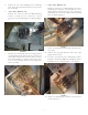
6. Remove the circuit breaker mounting bracket,
leaving the circuit breakers connected.
7. Remove the circuit breaker mounting bracket from
the heater element, leaving the circuit breakers
connected.
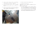
8. Attach the circuit breaker mounting bracket inside
the top left corner of the electric heat kit box (Figure
2). Ensure the breaker is oriented with OFF position
to the left. Remove the two (2) sheet metal screws
prior to installation and re-attach as shown in Figure
3.
NOTE: In some cases, it will be easier to wire the
breakers BEFORE inserting them into the electric heat
kit box.
CIRCUIT BREAKER
MOUNTING PLATE
FIGURE 2