
Installation Manual


2
S
HIPPING
I
NSPECTION
All units are securely packed in shipping containers tested
according to International Safe Transit Association specifi-
cations. The carton must be checked upon arrival for ex-
ternal damage. If damage is found, a request for inspec-
tion by carrier’s agent must be made in writing immedi-
ately.
Inspect the kit carefully on arrival for damage and bolts or
screws which may have come loose in transit. In the event
of damage the consignee should:
1. Make a notation on delivery receipt of any visible
damage to shipment or container.
2. Notify carrier promptly and request an inspection.
3. With concealed damage, carrier must be notified as
soon as possible - preferably within five days.
4. File the claim with the following support documents
within a nine month statute of limitations.
• Original or certified copy of the Bill of Lading, or
indemnity bond.
• Original paid freight bill or indemnity in lieu thereof.
• Original or certified copy of the invoice, showing
trade and other discounts or reductions.
• Copy of the inspection report issued by carrier’s
representative at the time damage is reported to
carrier.
The carrier is responsible for making prompt inspection of
damage and for a thorough investigation of each claim. The
distributor or manufacturer will not accept claims from
dealers for transportation damage.
S
TANDARD
A
IR
HANDLER
I
NSTALLATION
T
O
PREVENT
PERSONAL
INJURY
OR
DEATH
WHEN
INSTA LLING
IN
A
GARAGE
,
THE
ELEMENT
MUST
BE
AT
LEA ST
18”
ABOVE
THE
FLOOR
.
WARNING
T
O
AVOID
PROPERTY
DAMAGE
OR
PERSONAL
INJURY
DUE
TO
FIRE
,
USE
ONLY
COPPER
CONDUCTORS
..
CAUTION
NOTE: When installing in a garage, the element MUST be
at least 18” above the floor.
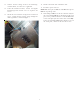
1. Remove the upper access panel from the air handler.
2. Remove the block-off plate from the air handler.
3. Slide the heater kit into the slot following the
direction of airflow decal attached to the heater
faceplate and secure using the screws previously
removed.
Items 4 through 7 & 10 pertain to kits
that contain circuit breakers.
4. Remove the circuit breaker mounting bracket,
leaving the circuit breakers connected.
5. AR, ARUF, ARPF, AEPF, ASPF, AVPTC, MBVC, MBE
and MBR models
Mount the circuit breaker mounting bracket as shown
using the supplied screws. Insert two of the screws
through the blower deck from the blower side. Insert
the remaining screws in the holes provided on the
upper right side of the jacket.
NOTE: HKA-15C replaces HKR-15C and HKA-20C replaces
HKR-20C in air handlers.
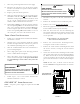
CIRCUIT
BREAKER
MOUNTING
PLATE
FIGURE 1
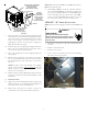
6. Insert the breaker with OFF position oriented down.
NOTE: In the horizontal position, the direction does
not matter. In some cases, it will be easier to wire
the breakers before reinserting them into the
mounting bracket.
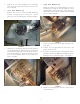
7. Insert power leads into the lugs provided on the
circuit breaker and tighten. The power leads MUST
be routed through a strain relief as they enter the
cabinet.
HIGHVOL TAGE!
TO
AVOID
THE
RISK
OF
ELECT RICAL
SHOCK
,
A
MEANS
OF
STRAIN
RELIEF
AND
CONDUCTOR
PROTECTION
MUST
BE
PROVIDED
AT
THE
SUPPLY
WIRE
ENTRANCE
.
WARNING
8. Remove the multi-pin connector with the jumper wire
and discard. Insert the one contained in the kit. It
can be inserted in one position only.