
Service Manual

SERVICING
32
If the valve fails to change its position, test the voltage (24V) at
the valve coil terminals, while the system is on the COOLING
cycle.
If no voltage is registered at the coil terminals, check the op-
eration of the thermostat and the continuity of the connecting
wiring from the "O" terminal of the thermostat to the unit.
If voltage is registered at the coil, tap the valve body lightly
while switching the system from HEATING to COOLING, etc.
If this fails to cause the valve to switch positions, remove the
coil connector cap and test the continuity of the reversing valve
solenoid coil. If the coil does not test continuous - replace it.
If the coil test continuous and 24 volts is present at the coil
terminals, the valve is inoperative - replace it.
S-24 TESTING DEFROST CONTROL
NOTE: PCBDM133 and PCBDM160 defrost controls have a
three (3) minute compressor off cycle delay.
NOTE: The PCBDM133 and PCBDM160 defrost controls are
shipped from the factory with the compressor delay option
selected. This will de-energize the compressor contactor for
30 seconds on defrost initiation and defrost termination. If the
jumper is set to Normal, the compressor will continue to run
during defrost initiation and defrost termination. The control
will also ignore the low pressure switch connected to R-PS1
and PS2 for 5 minutes upon defrost initiation and 5 minutes
after defrost termination.
To check the defrost control for proper sequencing, proceed as
follows: With power ON; unit not running.
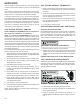
1. Jumper defrost thermostat by placing a jumper wire across
the terminals "DFT" and "R" ("R-DFT" on PCBDM133 and
PCBDM160) at defrost control board.
2. Connect jumper across test pins on defrost control board.
3. Set thermostat to call for heating. System should go into
defrost within 21 seconds.
4. Immediately remove jumper from test pins.
5. Using VOM check for voltage across terminals "C & O"
("O-RV" on PCBDM133 and PCBDM160). Meter should
read 24 volts.
6. Using VOM check for voltage across fan terminals DF1
and DF2 on the board. You should read line voltage (208-
230 VAC) indicating the relay is open in the defrost mode.
7. Using VOM check for voltage across "W2" (W on
PCBDM133 and PCBDM160) & "C" terminals on the board.
You should read 24 volts.
8. If not as above, replace control board.
9. Set thermostat to off position and disconnect power before
removing any jumpers or wires.
NOTE: Remove jumper across defrost thermostat before re-
turning system to service.
S-25 TESTING DEFROST THERMOSTAT
1. Install a thermocouple type temperature test lead on the
tube adjacent to the defrost control. Insulate the lead point
of contact.
2. Check the temperature at which the control closes its con-
tacts by lowering the temperature of the control. It should
close at approximately 32°F ± 2°F.
3. Check the temperature at which the control opens its con-
tacts by raising the temperature of the control. It should
open at approximately 60°F.
4. If not as above, replace control.
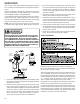
S-50 CHECKING HEATER LIMIT CONTROL(S)
(OPTIONAL ELECTRIC HEATERS)
Each individual heater element is protected with an automatic
rest limit control connected in series with each element to
prevent overheating of components in case of low airflow. This
limit control will open its circuit at approximately 150°F. to
160°F and close at approximately 110°F.
WARNING
DISCONNECT ELECTRICAL POWER SUPPLY.
1. Remove the wiring from the control terminals.
2. Using an ohmmeter test for continuity across the normally
closed contacts. No reading indicates the control is open
- replace if necessary. Make sure the limits are cool before
testing.
IF FOUND OPEN - REPLACE - DO NOT WIRE AROUND.
S-52 CHECKING HEATER ELEMENTS
Optional electric heaters may be added, in the quantities shown
in the spec sheet for each model unit, to provide electric resis-
tance heating. Under no condition shall more heaters than the
quantity shown be installed.
WARNING
1. Disassemble and remove the heating element(s).
2. Visually inspect the heater assembly for any breaks in the
wire or broken insulators.
3. Using an ohmmeter, test the element for continuity - no
reading indicates the element is open. Replace as neces-
sary.