
Kit Instructions

3. Remove one wire at a time from the existing circuit breaker
and locate on the same connection of the new circuit
breaker being installed. Proceed with this process on all
circuit breaker wires. Use the wiring diagram provided on
Heater Kit to make sure the wiring is correct.
NOTE: If Siemens circuit breakers are being replaced, mount-
ing bracket (B) provided in the kit can be discarded.
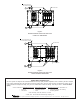
4. Unfasten the two # 10x½” screws and remove mounting
bracket (B) at the top of the breaker as shown in Figure 2.
Slide the existing Siemens breaker off the bottom bracket
and then slide the new Siemens breaker onto the bottom
bracket. Reassemble mounting bracket (B) to the top of
the breaker and refasten with the two # 10x½” screws.
5. If G.E. circuit breakers are being replaced with a Siemens
Circuit Breaker, remove both the top and bottom (A) mount-
ing brackets by removing the two # 10x½” screws per
mounting bracket that secure them to the mounting plate.
G.E. breakers located per Figure 1.
6. Relocate mounting bracket (A) at dimension (1.907”) from
the bottom of the circuit breaker plate as shown in Figure
2 and fasten with two of the # 10x½” screws that were
previously removed in Step 5. Slide the Siemens circuit
breaker onto the bottom bracket flanges. Next, insert the
mounting bracket (B) that was provided in the kit at dimen-
sion (.875”) from the top of the circuit breaker plate as
shown in Figure 2 and fasten with two of the # 10x½” screws
that were previously removed in Step 5 .
7. To ensure the Siemens Circuit Breaker is assembled in
the correct location, there must be two unused holes seen
at the bottom and top of the mounting brackets.
NOTE: If the Siemens Circuit Breaker is not located in the
correct position, the breaker will not line up with the breaker
window on the access panel.
8. Reinstall the access panel on the airhandler or package
unit.
9. Restore power to unit. Set the thermostat to call for elec-
tric heat mode of operation.
10. Verify system is functioning correctly.
Attention Installing Personnel
As a professional installer, you have an obligation to know the
product better than the customer. This includes all safety
precautions and related items.
Prior to actual installation, thoroughly familiarize yourself with
this Instruction Manual. Pay special attention to all safety
warnings. Often during installation or repair, it is possible to
place yourself in a position which is more hazardous than
when the unit is in operation.
Remember, it is your responsibility to install the product safely
and to know it well enough to be able to instruct a customer in
its safe use.
Safety is a matter of common sense...a matter of thinking
before acting. Most dealers have a list of specific good safety
practices...follow them.
The precautions listed in this Installation Manual are intended
as supplemental to existing practices. However, if there is a
direct conflict between existing practices and the content of
this manual, the precautions listed here take precedence.
Description
These installation instructions are for installing the following
Circuit Breaker Kits.
These kits contain the following parts: Siemens Circuit Break-
ers, Mounting Bracket and Installation Instructions. See
Figures 1 and 2 for mounting bracket instructions.
WARNING
HIGH VOLTAGE!
DISCONNECT ALL POWER BEFORE SERVICING OR INSTALLING
THIS UNIT.
MULTIPLE POWER SOURCES MAY BE PRESENT. FAILURE
TO DO SO MAY CAUSE PROPERTY DAMAGE, PERSONAL INJURY OR
DEATH.
CAUTION
TO AVOID POSSIBLE PERSONAL INJURY, USE EXTREME CAUTION IF USING
POWER TOOLS TO REMOVE THE SMALL BREAKER MOUNTING BRACKETS.
T
HE
BRACKETS MAY QUICKLY ROTATE AND CAUSE INJURY.
1. Disconnect all power to the unit, both indoor and outdoor.
2. To replace circuit breakers in airhandlers or package elec-
tric units with heater kits already installed, the access
panel must be removed.
NOTE: When changing wires from the existing circuit breaker
to the new circuit breaker, it may be necessary to use needle
nose pliers.
HKR / HKA / HKP CIRCUIT BREAKER KIT
(WITH SIEMENS CIRCUIT BREAKER)
INSTALLATION INSTRUCTIONS
IO-319C
12/2013