
Service Manual

SERVICING
26
SINGLE PHASE
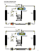
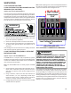
1. Disconnect the wire leads from the terminal (T) side of the
contactor.
2. With power ON, energize the contactor.
WARNING
LINE VOLTAGE NOW PRESENT.
VOLT/OHM
METER
T1
T2
L1L2
CC
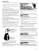
Ohmmeter for testing holding coil
Voltmeter for testing contacts
TESTING COMPRESSOR CONTACTOR
(Single Phase)
3. Using a voltmeter, test across terminals.
A. L1 to L2 - No voltage. Check breaker or fuses on main
power supply. If voltage present, proceed to step B.
B. T1 to T2 - Meter should read the same as L1 to L2 in
step A. If voltage readings are not the same as step A,
replace contactor.
S-9 CHECKING FAN RELAY CONTACTS
The Electronic Blower Time Delay Relay is used on models
equipped with PSC type blower motors.
WARNING
Checking EBTDR High Voltage Contacts
1. With power off, remove wires from terminals NC, COM, and
NO.
2. Using a VOM, check for resistance from NO to COM. Should
read open. Next, check for resistance from NC to COM.
Should read closed.
3. If not as in steps 1 and 2, replace EBTDR.
Checking EBTDR Contact Operation
With power on:
WARNING
LINE VOLTAGE NOW PRESENT.
1. Set the thermostat to the fan "on" position.
2. Check for 24 volts at the C and G terminals of the EBTDR.
3. If no voltage present, check fan circuit from thermostat. If
24 volts present, proceed to step 4.
4. Using a VOM, check for line voltage from the purple wire at
the transformer (terminal 3 on 240 volt units, terminal 2 on
208 volt units) to terminal NO on the EBTDR. Should read
line voltage. If no voltage present, check line voltage wiring
in unit. If line voltage present, proceed to step 5.
5. Using a VOM, check for line voltage from the purple wire at
the transformer (terminal 3 on 240 volt units, terminal 2 on
208 volt units) to the COM terminal on the EBTDR. Should
read line voltage. If not as above, replace EBTDR.
PSC Type Blower Motor Models Only
Heat pump and cooler models equipped with PSC type blower
motors have an isolation relay with a 240 volt holding coil in
addition to the EBTDR.
WARNING
DISCONNECT POWER SUPPLY BEFORE SERVICING.
Turn power off.
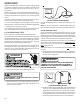
Testing relay holding coil
1. Remove the leads from the holding coil terminals 1 and 3.
2. Using an ohmmeter, test across the coil terminals 1 and 3.
If the coil does not test continuous, replace the relay.
Testing relay contacts
WARNING
DISCONNECT POWER SUPPLY BEFORE SERVICING.
Turn power off.
1. Using a VOM, test resistance across relay terminals 2 and
4. Should read open.
2. Turn power on.