
Installation Manual

6
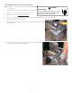
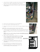
FIGURE 9
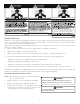
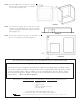
NOTE: To replace the electric heat kit cover, slightly tip
the cover and insert
only the notches under the flanges
on the top and bottom of the box. Secure with screws.
See Figure 7.
18. Ensure breaker is in the ON position. Replace blower panel
cover and check operation through the room thermostat.
19. RESTORE POWER.
20. Apply the provided wiring diagram for package unit models
adjacent to the wiring diagram supplied on the inside of
the unit control box cover.
21. When proper operation is ensured, replace the control
box cover and resume normal operation.
NOTE:
In Package Units:
HKP-05C replaces HKR-05C HKP-10C replaces HKR-10C
HKP-15C replaces HKR-15C HKP-20C replaces
HKR-20C
22. If installing an HKP heater kit on a unit that only has the
corresponding HKR heater kit shown on the serial plate,
use a permanent marker to add the HKP model to the
serial plate (the data is the same as the HKR). If the
corresponding HKR model number is not on the serial
plate, the heater kit can not be used.
“M” S
ERIES
P
ACKAGE
U
NIT
I
NSTALLATION
NOTE: A separate power supply is required for the HKR
heater kits.
1. Disconnect all power to the unit, both indoor and
outdoor.
2. Remove control box door.
3. Remove blower door.
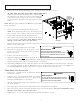
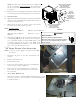
4. Locate heater box. Remove the two screws holding the
heater box cover in place (Figure 8).
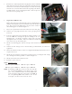
5. Remove the two screws holding the rear mounting
plate. Note the orientation of the heater box covers
for reassembly.
6. Three-Phase HKR Kits only
Remove the contactor from the HKR mounting bracket, leaving
the wires connected. Attach contactor to rear mounting plate
as shown in Figure 9.
HIGH VOLTAGE !
D
ISCONNECT
ALL
POWER
BEFORE
SERVICING
.
M
ULTIPLE
POWER
SOURCES
MAY
BE
PRESENT
. F
AILURE
TO
DO
SO
MAY
CAUSE
PROPERTY
DAMAGE
,
PERSONAL
INJURY
OR
DEATH
.
WARNING
FIGURE 8
ATTACH CIRCUIT BREAKER
MOUNTING BRACKET
WITH PROVIDED
SHEET METAL SCREW
TIP IN SLIGHTLY
AND SECURE
NOTCHES
BEHIND FLANGE
FLANGE
CIRCUIT
BREAKER
KNOCKOUTS
SCREW
A
TTACH CIRCUIT BREAKER
MOUNTING BRACKET
WITH PROVIDED
SHEET METAL SCREW
FIGURE 7