
HKP Service Manual

SERVICING
35
S-103 CHARGING
WARNINGWARNING
CAUTION
CAUTION
Charge the system with the exact amount of refrigerant.
Refer to the specification section or check the unit nameplates
for the correct refrigerant charge.
After completing airflow measurements and adjustments, the
unit’s refrigerant charge must be checked. The unit comes
factory charged, but this charge is based on 400 CFM per ton
at minimum ESP per AHRI test conditions (generally between
.15 - .25 ESP). When air quantity or ESP is different than
above, charge must be adjusted to the proper amount.
All package units are charged to the superheat method at the
compressor suction line (these are fixed orifice devices).
For charging in the warmer months, 10
0
F superheat at the com-
pressor is required at conditions: 95
0
F outdoor ambient (dry
bulb temperature), 80
0
F dry bulb / 67
0
F wet bulb indoor ambi-
ent, approximately 50% humidity. This superheat varies when
conditions vary from the conditions described.
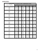
A superheat charge chart is available for other operating condi-
tions. Use it to provide the correct superheat at the conditions
the unit is being charged at.
After superheat is adjusted it is recommended to check unit
sub-cooling at the condenser coil liquid line out. In most oper-
ating conditions 12 + 4
0
F of sub-cooling is adequate.
An inaccurately charged system will cause future problems.
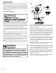
1. Using a quality set of charging scales, weigh the proper
amount of refrigerant for the system. Allow liquid refrigerant
only to enter the high side.
2. After the system will take all it will take, close the valve on
the high side of the charging manifold.
3. Start the system and charge the balance of the refrigerant
through the low side.
NOTE: R410A should be drawn out of the storage con-
tainer or drum in liquid form due to its fractionation proper-
ties, but should be "Flashed" to its gas state before enter-
ing the system. There are commercially available restric-
tion devices that fit into the system charging hose set to
accomplish this. DO NOT charge liquid R410A into the
compressor.
4. With the system still running, close the valve on the charg-
ing cylinder. At this time, you may still have some liquid
refrigerant in the charging cylinder hose and will definitely
have liquid in the liquid hose. Slowly open the high side
manifold valve and transfer the liquid refrigerant from the
liquid line hose and charging cylinder hose into the suction
service valve port. CAREFUL: Watch so that liquid refrig-
erant does not enter the compressor.
Final Charge Adjustment
The outdoor temperature must be 60°F or higher. Set the room
thermostat to COOL, fan switch to AUTO, and set the tem-
perature control well below room temperature.
After system has stabilized per start-up instructions, compare
the operating pressures and outdoor unit amp draw to the num-
bers listed in the technical manual. If pressures and amp draw
are too low, add charge. If pressures and amp draw are too
high, remove charge. Check subcooling and superheat as de-
tailed in the following section.
5. With the system still running, remove hose and reinstall
both access fitting caps.
6. Check system for leaks.
Due to their design, Scroll compressors are inherently more
tolerant of liquid refrigerant.
NOTE: Even though the compressor section of a Scroll com-
pressor is more tolerant of liquid refrigerant, continued flood-
back or flooded start conditions may wash oil from the bearing
surfaces causing premature bearing failure. S-104 CHECK-
ING COMPRESSOR EFFICIENCY
The reason for compressor inefficiency is broken or damaged
suction and/or discharge valves, or scroll flanks on Scroll com-
pressors, reducing the ability of the compressor to pump re-
frigerant vapor.