
HKP Service Manual

SERVICING
31
3. If a ground is indicated, then carefully remove the compres-
sor terminal protective cover and inspect for loose leads or
insulation breaks in the lead wires.
4. If no visual problems indicated, carefully remove the leads
at the compressor terminals.
Carefully retest for ground, directly between compressor
terminals and ground.
5. If ground is indicated, replace the compressor.
S-17D OPERATION TEST
If the voltage, capacitor, overload and motor winding test fail to
show the cause for failure:
WARNING
1. Remove unit wiring from disconnect switch and wire a test
cord to the disconnect switch.
NOTE: The wire size of the test cord must equal the line wire
size and the fuse must be of the proper size and type.
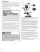
2. With the protective terminal cover in place, use the three
leads to the compressor terminals that were disconnected
at the nearest point to the compressor and connect the
common, start and run clips to the respective leads.
3. Connect good capacitors of the right MFD and voltage rat-
ing into the circuit.
4. With power ON, close the switch.
WARNING
LINE VOLTAGE NOW PRESENT.
A. If the compressor starts and continues to run, the
cause for failure is somewhere else in the system.
B. If the compressor fails to start - replace.
The condition of the scroll flanks is checked in the following
manner.
1. Attach gauges to the high and low side of the system.
2. Start the system and run a “Cooling Performance Test.
If the test shows:
a. Below normal high side pressure.
b. Above normal low side pressure.
c. Low temperature difference across coil.
d. Low amp draw at compressor.
and the charge is correct, test the reversing valve if equipped
(heat pump models only. See-S-21). If the reversing valves
test good, the compressor is faulty - replace the compressor.
S-18 TESTING CRANKCASE HEATER
(OPTIONAL ITEM)
Note: Not all compressors use crankcase heaters.
The crankcase heater must be energized a minimum of twenty-
four (24) hours before the compressor is operated.
Crankcase heaters are used to prevent migration or accumula-
tion of refrigerant in the compressor crankcase during the off
cycles and prevents liquid slugging or oil pumping on start up.
On some models, the crankcase heater is controlled by a crank-
case heater thermostat that is wired in series with the crank-
case heater.
A crankcase heater will not prevent compressor damage due
to a floodback or over charge condition.
WARNING
DISCONNECT POWER SUPPLY BEFORE SERVICING.
1. Disconnect the heater lead wires.
2. Using an ohmmeter, check heater continuity - should test
continuous, if not, replace.
S-18A CHECKING CRANKCASE HEATER
THERMOSTAT
Note: Not all models with crankcase heaters will have a
crankcase heater thermostat.
1. Install a thermocouple type temperature test lead on the
discharge line adjacent to the crankcase heater thermo-
stat.
2. Check the temperature at which the control closes its con-
tacts by lowering the temperature of the control. The crank-
case heater thermostat should close at 67°F ± 5°F.
3. Check the temperature at which the control opens its con-
tacts by raising the temperature of the control. The crank-
case heater thermostat should open at 85°F ± 5°F.
4. If not as above, replace control.