
Service Manual

SERVICING
36
CAUTION
To prevent personal injury, carefully connect and
disconnect manifold gauge hoses. Escaping liquid
refrigerant can cause burns. Do not vent refrigerant
to atmosphere. Recover during system repair
or final unit disposal.
1. Run system at least 10 minutes to allow pressure to sta-
bilize.
2. Temporarily install thermometer on suction (large) line
near compressor with adequate contact and insulate for
best possible reading.
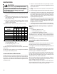
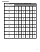
3. Refer to the superheat table provided for proper system
superheat. Add charge to lower superheat or recover
charge to raise superheat.
Superheat Formula = Suct. Line Temp. - Sat. Suct. Temp.
100
-
-
-
10 10
95
- - 10 10 10
90
- - 12 15 18
85
- 10 13 17 20
80
- 10 15 21 26
75 10 13 17 25 29
70 10 17 20 28 32
65 13 19 26 32 35
60 17 25 30 33 37
Ambient Condenser
Inlet Temp (°F
Drybulb)
65 70 75
Return Air Temp. (°F Drybulb)
80 85
EXAMPLE:
a. Suction Pressure = 143
b. Corresponding Temp. °F. = 50
c. Thermometer on Suction Line = 59°F.
To obtain the degrees temperature of superheat, subtract 50.0
from 59.0°F.
The difference is 9° Superheat. The 9° Superheat would fall in
the ± range of allowable superheat.
S-109 CHECKING SUBCOOLING
Refrigerant liquid is considered subcooled when its tempera-
ture is lower than the saturation temperature corresponding to
its pressure. The degree of subcooling equals the degrees of
temperature decrease below the saturation temperature at the
existing pressure.
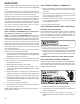
1. Attach an accurate thermometer or preferably a thermo-
couple type temperature tester to the liquid line close to
the pressure switch.
2. Install a high side pressure gauge on the liquid access
fitting.
3. Record the gauge pressure and the temperature of the line.
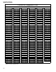
4. Compare the hi-pressure reading to the "Required Liquid
Line Temperature" chart. Find the hi-pressure value on the
left column. Follow that line right to the column under the
design subcooling value. Where the two intersect is the
required liquid line temperature.
Alternately you can convert the liquid line pressure gauge
reading to temperature by finding the gauge reading in Tem-
perature - Pressure Chart and reading to the left, find the
temperature in the °F. Column.
5. The difference between the thermometer reading and pres-
sure to temperature conversion is the amount of subcooling.
Subcooling Formula = Sat. Liquid Temp. - Liquid Line
Temp.
EXAMPLE:
a. Liquid Line Pressure = 417
b. Corresponding Temp. °F. = 120°
c. Thermometer on Liquid line = 109°F.
To obtain the amount of subcooling, subtract 109°F from 120°F.
The difference is 11° subcooling. See the specification sheet
or technical information manual for the design subcooling range
for your unit.
See R410A Pressure vs. Temperature chart.
S-111 FIXED ORIFICE RESTRICTION
DEVICES
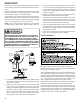
The fixed orifice restriction device (flowrator) used in conjunc-
tion with the indoor coil is a predetermined bore (I.D.).
It is designed to control the rate of liquid refrigerant flow into an
evaporator coil.
The amount of refrigerant that flows through the fixed orifice
restriction device is regulated by the pressure difference be-
tween the high and low sides of the system.
In the cooling cycle when the outdoor air temperature rises,
the high side condensing pressure rises. At the same time,
the cooling load on the indoor coil increases, causing the low
side pressure to rise, but at a slower rate.
Since the high side pressure rises faster when the tempera-
ture increases, more refrigerant flows to the evaporator, increas-
ing the cooling capacity of the system.
When the outdoor temperature falls, the reverse takes place.
The condensing pressure falls, and the cooling loads on the
indoor coil decreases, causing less refrigerant flow.