
Installation Manual

5
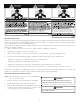
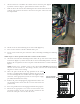
8. Attach contactors to included “H” model vertical contactor plate (Figure
4). Ensure contactor lugs are pointed inward towards each other.
9. Slide the heater kit into the slot following the direction of airflow decal for
package unit operation attached to the heater faceplate and secure with
screws provided.
FIGURE 4
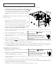
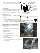
10. Install two of the four mounting screw on heaterkit (Figure 5).
11. Place vertical contactor bracket behind corner post.
12. Secure vertical contactor plate and heater kit to unit using remaining two mounting
screws.
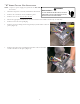
NOTE: Steps 13 and 16 pertain to kits that contain circuit breakers.
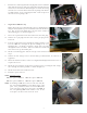
13. Attach the circuit breaker mounting bracket inside the top left corner of the electric
heat kit box (Figure 6). Ensure the breaker is oriented with OFF position to the left.
Remove the two (2) sheet metal screws prior to installation and re-attach as shown in
Figure 7.
NOTE: In some cases, it will be easier to wire the breakers BEFORE inserting them
into the electric heat kit box. If rewiring is desired, reference the included wiring
diagram to ensure correct wiring.
14. Insert the power leads into the lugs provided on the circuit
breaker or terminal block and tighten. Ensure the power leads
are routed through the outer cabinet with a watertight electrical
connector, sized appropriately for the electrical power supply
(see NEC, National Electric Code).
15. Remove the protection plug (male plug) and discard. Insert the
one provided in the electric heat kit. It can be inserted in one
position only.
16. Insert the ground wire into the lug(s) provided for that purpose.
17. Break out the appropriate area of the electric heat kit cover
previously removed for the circuit breaker provided in the
heater kit and replace electric heat kit cover.
FIGURE 5
CIRCUIT BREAKER
MOUNTING PLATE
FIGURE 6