
Installation Instructions

4
1. Connect a calibrated water manometer or appropriate
gas pressure gauge at either the gas valve inlet pressure
tap or gas piping drip leg. The gas supply and manifold
pressure on White-Rodgers 36J54 gas valves, used on
single and two stage furnaces, can be checked with a gas
pressure test kit (Part # 0151K00000S) available through
our authorized distributors.
2. Turn ON the power and gas, put the unit into heating
cycle and turn on all other gas consuming appliances.
3. Leak check burner orifice threads using soap solution.
4. Measure the gas supply pressure with the burners firing.
The inlet gas pressure for natural gas should be between
5.0 and 10.0 inches W.C. The inlet gas pressure for
propane gas must be between 11.0 and 13.0 inches W.C.
If supply pressure differs from required, make necessary
adjustments to pressure regulator(s), gas piping, etc.
5. Turn OFF gas to the unit at the manual shutoff valve and
disconnect manometer. Reinstall line pressure tap plug.
Turn OFF any unnecessary appliances started in step 2.
Inlet
Pressure
Boss
Low Fire
Regulator
Adjust
M
a
n
o
m
e
t
e
r
M
a
n
o
m
e
t
e
r
H
o
s
e
High Fire Regulator
Adjust
Regulator
Vent
Outlet
Pressure Boss
Open to
Atmosphere
O
n
/
O
f
f
S
w
i
t
c
h
H
i
g
h
F
i
r
e
C
o
i
l
T
e
r
m
i
n
a
l
(
H
I
)
C
o
a
x
i
a
l
C
o
i
l
T
e
r
m
i
n
a
l
(
M
)
Common
Terminal(C)
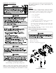
Figure 3
White-Rodgers Model 36J54 Connected to Manometer
MANIFOLD PRESSURE CHECK
Only small variations in gas flow should be made by adjusting
the gas valve pressure regulator. See Table 3 for the required
natural gas manifold pressure and see Table 4 for the re-
quired propane gas manifold pressure.
Low Stage High Stage
1.6 to 2.2" w.c. 3.2 to 3.8" w.c.
Natural Gas Manifold Pressure
Table 3
Low Stage High Stage
5.7 to 6.3" w.c. 9.7 to 10.3" w.c.
Propane Gas Manifold Pressure
Table 4
1. Turn OFF gas to the unit at the manual gas shutoff valve.
2. Connect a calibrated water manometer or appropriate
gas pressure gauge at the gas valve outlet pressure tap.
The gas supply and manifold pressure on White-Rodgers
36J54 gas valves, used on single and two stage furnaces,
can be checked with a gas pressure test kit (Part #
0151K00000S) available through our authorized
distributors.
3. Turn ON gas supply and operate unit.
4. Remove the cap screw from the high stage manifold
pressure regulator adjustment location.
5. Using an Allen wrench, adjust high stage manifold regulator
to the required manifold pressure (Table 3 for Natural
Gas or Table 4 for Propane Gas).
6. Reinstall the high stage manifold pressure regulator cap
screw. Confirm high stage manifold pressure.
7. Remove the cap screw from the low stage manifold
pressure regulator adjustment location.
8. Using an Allen wrench, adjust low stage manifold regulator
to the required manifold pressure.
9. Reinstall the low stage manifold regulator cap screw.
Confirm low stage manifold pressure.
10. Turn OFF gas supply to unit. Disconnect manometer and
reinstall manifold pressure tap plug.
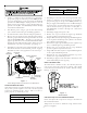
INSPECT BURNER FLAME
The burner flames should be stable, soft and blue (dust may
cause orange tips but they must not be yellow). They should
extend directly outward from the burners without curling,
floating, or lifting off.
Figure 4
Burner Flame
CHECK AND ADJUST UNIT TEMPERATURE RISE
Check and adjust unit temperature rise(s) as described in
the installation manual.
Temperature rise must be within the range shown on the
furnace rating plate.