
Installation Instructions

3
4. Remove the screws securing the gas manifold and valve
to the burner bracket and retain. Separate gas manifold
and valve from burner bracket.
NOTE: If Natural Gas conversion proceed to step 5 and
upon completion of step 5 skip to step 9.
If Propane Gas conversion skip step 5 and jump to step 6
PROPANE GAS BURNER ORIFICE and GAS VALVES SPRING RE-
PLACEMENT step.
5. NATURAL GAS BURNER ORIFICE REPLACEMENT
a. Remove standard altitude natural gas orifices from
gas manifold using a box end wrench.
b. Visually inspect Natural gas high altitude orifices
(B2589907) for damage and drill size (marked on face
with #49) before installation. Using 7/16" box-end
wrench, remove all existing #45 natural gas orifices
and replace with the appropriate #49 natural gas high
altitude orifices supplied in the kit. Tighten orifices
with a box-end wrench; do not cross-thread or over-
tighten. Orifice usage depends on an installation’s
gas usage and altitude.
6. PROPANE GAS BURNER ORIFICE AND GAS VALVES SPRING
REPLACEMENT
IMPORTANT: propane gas is heavier than air and
does not vent upward as natural gas fuels.
a. Remove standard altitude natural gas orifices from
gas manifold using a box end wrench.
b. Visually inspect Propane gas high altitude orifices
(B2589908) for damage and drill size (marked on
face with #56) before installation. Using 7/16" box-
end wrench, remove all existing #45 natural gas
orifices and replace with the appropriate #56 pro-
pane gas high altitude orifices supplied in the kit.
Tighten orifices with a box-end wrench; do not
cross-thread or overtighten. Orifice usage depends
on an installation’s gas usage and altitude.
c. Remove both regulator cover screws from gas
valve.
d. Using a ¼” flat blade screwdriver, remove both
regulator adjustment screws (beneath the cover
screw),
e. Remove both Natural gas regulator springs (color-
coded silver/plain) from regulator sleeves and re-
tain with the Natural Gas orifices for future
reconversion.
f. Insert the L.P. regulator springs (provided in the
conversion kit and color-coded white) into the
regulator sleeves.
7. Replace the High regulator adjustment screw and ad-
just until screw reaches the bottom stop, then follow
the instructions in the Adjustment and Checks section
to verify manifold pressure falls into the desired range.
See Table 4.
8. Replace the Low regulator adjustment screw and adjust
until screw reaches the bottom stop, then follow the in-
structions in the Adjustment and Checks section to
verify manifold pressure falls into the desired range.
See Table 4.
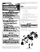
9. PRESSURE SWITCH ASSEMBLY INSTALLATION
a. Locate two-stage pressures switch assembly lo-
cated on the induced draft blower.
NOTE: Single pressure switch with two gray wires
does not require a change.
b. Disconnect the pressure switch hose from the pres-
sure switch assembly tee.
c. Disconnect high stage (yellow and orange) and low
stage (brown and orange) wiring from pressure
switches.
d. Remove mounting bracket screw securing standard
altitude pressure switch assembly to induced draft
blower.
e. Install high altitude pressure switch assembly
0130F00497 using screw removed in Step 4.
f. Reconnect wiring to pressure switch assembly.
g. Reconnect pressure switch hose to new assembly.
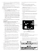
Induced
Draft Blower
Pressure
Switches
Gas
Valve
Figure 2
(Upflow shown, counterflow similar)
ADJUSTMENTS AND CHECKS
The following adjustments and checks are a required part of
this conversion. Adjustment and checks include:
• Leak checking orifices.
• Checking and adjusting line and manifold gas pressures.
• Verifying proper unit operation (input rate, operational
sequence, burner flame, temperature rise, etc.).