
Installation Instructions

2
IMPORTANT INFORMATION
Contact a local propane gas supplier
about installing a gas detecting warning device.
NOTE: To ensure proper operation, install, operate and
maintain the unit in accordance with these installation in-
structions, all local building codes and ordinances. In their
absence, follow the latest edition of the National Fuel Gas
Code (NFPA 54/ANSI Z223.1), and/or CAN/CSA B149.1 In-
stallation Codes.
HASFK-1
The conversion from “standard altitude” natural gas orifices
and pressure switch assembly (as shipped from the factory)
to “high altitude” natural or propane orifices and pressure
switch assembly requires the following tools and supplies:
• 1 - 7/16” box wrench
• 1 - 1/4” nut driver
• 1 - 3/16” allen wrench
• 1 - 1/4” flat blade screwdriver
• 1 - Manometer to read inlet and outlet pressure of the
gas valve (minimum range: 0” - 20” W.C.)
• Gas leak detection solution like soap and water solu-
tion. always wipe the solution from the joints when
testing is completed.
Before proceeding, shut OFF gas supply at manual shut-off
and turn off power to the unit.
ORIFICE AND PRESSURE SWITCH ASSEMBLY INSTALLA-
TION
1. Shut OFF gas supply at manual shutoff and turn OFF
power to the unit.
2. Remove access door.
3. Disconnect wiring from the gas valve.
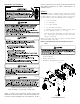
Burner Bracket
Burner
Gas Valve
Manifold
Figure 1
Gas Manifold Removal