
Installation Instructions
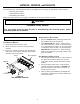
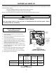
Table Of Contents
- Contents
- General Information
- HANG13, HANG14, and HALP11
- Orifice Installation
- Gas Manifold Removal
- Burner Orifice Replacement
- Gas Manifold Re-Installation
- Adjustments and Checks - HANG13 & 14
- Orifice Leak Check
- Line Pressure Check
- Manifold Pressure Check
- Unit Operation Checks - HANG13 & 14
- Check Normal Operating Sequence of Ignition System
- Verify Gas Input Rate(s)
- Inspect Burner Flame
- Check and Adjust Unit Temperature Rise
- Adjustments and Checks - HALP11
- Orifice Leak Check
- Line Pressure Check
- Manifold Pressure Check
- Unit Operation Checks - HALP11
- Check Normal Operating Sequence of Ignition System
- Verify Gas Input Rate(s)
- Inspect Burner Flame
- Check and Adjust Unit Temperature Rise
- Label Attachment
- HAPS28 and HAPS 29
- Pressure Switch Assembly
- Removal/Replacement

8
HAPS28 and HAPS 29
The conversion from “standard altitude” pressure switch assembly (as shipped from the factory) to “high altitude” pressure
switch assembly requires:
• Removing standard altitude two-stage pressure switch assembly
• Installing high altitude two-stage pressure switch assembly
Before proceeding, shut OFF gas supply at manual shut-off and turn OFF power to the unit.
Pressure Switch Assembly
Removal/Replacement
1. Locate induced draft blower two-stage pressure
switch assembly.
2. Disconnect the pressure switch hose from the pres-
sure switch assembly tee.
3. Disconnect high stage (yellow and orange) and low
stage (red and blue) wiring from pressure switches.
4. Remove mounting bracket screw securing standard
altitude assembly to partition panel.
5. Install high altitude pressure switch assembly using
screw removed in step 4. Refer to Table 1 for proper
pressure switch kit.
6. Reconnect high stage (yellow and orange) and low
stage (red and blue) wiring to pressure switches.
7. Reconnect pressure switch hose to new assembly.
8. Verify proper furnace operation.
Mounting
Bracket
Screw
Induced Draft Blower
Two-Stage
Pressure Switch
Assembly
Pressure Switch
Hose
Induced
Draft
Blower
Yellow/Orange, Red/Blue
Electrical Connections
*
*
*
**
*
*
M1
2
3P
C
ON
O
F
F
Figure 4
Induced Draft Blower
Pressure Switch Location
CAUTION
PERSONAL INJURY HAZARD
The gas supply must be shut off prior to disconnecting the electrical power, before
proceeding with the installation.
Table 7
Pressure Switch Kits
Kit
Two-Stage
Pressure
Switch
Assembl
y
Low Stage
Set Point
High Stage
Set Point
GUVA045**30
GUVA070**40
HAPS28 11177115 -0.22 -0.55
GUVA090**50
GUVA115**50
HAPS29 11177116 -0.38 -0.82
7,001 - 11,000 ft