
Installation Instructions
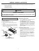
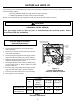
Table Of Contents
- Contents
- General Information
- HANG13, HANG14, and HALP11
- Orifice Installation
- Gas Manifold Removal
- Burner Orifice Replacement
- Gas Manifold Re-Installation
- Adjustments and Checks - HANG13 & 14
- Orifice Leak Check
- Line Pressure Check
- Manifold Pressure Check
- Unit Operation Checks - HANG13 & 14
- Check Normal Operating Sequence of Ignition System
- Verify Gas Input Rate(s)
- Inspect Burner Flame
- Check and Adjust Unit Temperature Rise
- Adjustments and Checks - HALP11
- Orifice Leak Check
- Line Pressure Check
- Manifold Pressure Check
- Unit Operation Checks - HALP11
- Check Normal Operating Sequence of Ignition System
- Verify Gas Input Rate(s)
- Inspect Burner Flame
- Check and Adjust Unit Temperature Rise
- Label Attachment
- HAPS28 and HAPS 29
- Pressure Switch Assembly
- Removal/Replacement

7
HANG13, HANG14, and HALP11
Adjustments and Checks - HALP11 Cont’d
LINE PRESSURE CHECK
1. Shut OFF gas at the manual gas shutoff valve and
turn OFF power to the unit.
2. Connect a calibrated water manometer or appropri-
ate gas pressure gauge at either the gas valve inlet
pressure tap or gas piping drip leg.
3. Turn ON the power and gas, put the unit into heating
cycle and turn on all other gas consuming appli-
ances.
4. Measure the gas supply pressure with the burners
firing. The inlet gas pressure for propane gas must
be between 11.0 and 13.0 inches W.C. If supply
pressure differs from required, make necessary ad-
justments to pressure regulator(s), gas piping, etc.
5. Turn OFF gas to the unit at the manual shutoff valve
and disconnect manometer. Reinstall line pressure
tap plug. Turn OFF any unnecessary appliances
started in step 3. See
Figure 2, page 5
.
MANIFOLD PRESSURE CHECK
Only small variations in gas flow should be made by
adjusting the gas valve pressure regulator. See Table 5
for the required propane gas manifold pressure.
Low Stage High Stage
5.7 to 6.3" W.C. 9.7 to 10.3" W.C.
Propane Gas Manifold Pressure(s)
Table 5
1. Turn OFF gas to the unit at the manual gas shutoff
valve.
2. Connect a calibrated water manometer or appropri-
ate gas pressure gauge at the gas valve outlet pres-
sure tap.
3. Turn ON gas supply and operate unit.
4. Remove the cap screw from the
low stage
manifold
pressure regulator adjustment location.
5. Using an Allen wrench, increase
low stage
manifold
pressure by adjusting the
low stage
manifold regula-
tor so the furnace will light and carry over.
6. Remove the cap screw from the
high stage
manifold
pressure regulator adjustment location.
7. Using an Allen wrench, adjust
high stage
manifold
regulator to the required manifold pressure (Table 5).
8. Reinstall the
high stage
manifold regulator cap
screw. Confirm
high stage
manifold pressure.
9. Using an Allen wrench, adjust
low stage
manifold
regulator to the required pressure.
10. Reinstall the low stage manifold regulator cap screw.
Confirm
low stage
manifold pressure.
11. Turn OFF gas supply to unit. Disconnect manometer,
reinstall manifold pressure tap plug.
Unit Operation Checks - HALP11
CHECK NORMAL OPERATING SEQUENCE OF IGNITION
SYSTEM
Check the normal operating sequence of the ignition
system to ensure burners light properly.
VERIFY GAS INPUT RATE(S)
Ensure that the appropriate orifices have been in-
stalled and the manifold pressure has been set as
specified in these instructions.
INSPECT BURNER FLAME
The burner flames should be stable, soft and blue
(dust may cause orange tips but they must not be
yellow). They should extend directly outward from
the burners without curling, floating, or lifting off.
CHECK AND ADJUST UNIT TEMPERATURE RISE
Check and adjust unit temperature rise(s) as de-
scribed in the installation manual.
Temperature rise must be within the range shown on
the furnace rating plate.
LABEL ATTACHMENT
Attach conversion data plate, with correct input rat-
ing, adjacent to the unit rating plate. Use Table 6 to
determine the correct data plate to be applied.
Size Models
High Stage Input
(BTU/hr)
Low Stage Input
(BTU/hr)
045 GUVA 41,400 32,000
070 GUVA 62,100 48,000
090 GUVA 82,800 64,000
115 GUVA 103,500 80,000
Two-Stage Units Input Rating
(Propane Gas: Standard Altitude)
Table 6
Post “conversion date certificate” adjacent to the unit
rating plate.