
Installation Instructions
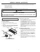
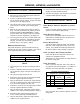
Table Of Contents
- Contents
- General Information
- HANG13, HANG14, and HALP11
- Orifice Installation
- Gas Manifold Removal
- Burner Orifice Replacement
- Gas Manifold Re-Installation
- Adjustments and Checks - HANG13 & 14
- Orifice Leak Check
- Line Pressure Check
- Manifold Pressure Check
- Unit Operation Checks - HANG13 & 14
- Check Normal Operating Sequence of Ignition System
- Verify Gas Input Rate(s)
- Inspect Burner Flame
- Check and Adjust Unit Temperature Rise
- Adjustments and Checks - HALP11
- Orifice Leak Check
- Line Pressure Check
- Manifold Pressure Check
- Unit Operation Checks - HALP11
- Check Normal Operating Sequence of Ignition System
- Verify Gas Input Rate(s)
- Inspect Burner Flame
- Check and Adjust Unit Temperature Rise
- Label Attachment
- HAPS28 and HAPS 29
- Pressure Switch Assembly
- Removal/Replacement

5
HANG13, HANG14, and HALP11
Adjustments and Checks - HANG13 & 14
The following adjustments and checks are required part
of this conversion. Adjustments and checks include:
• Leak checking orifices
• Checking and adjusting line and manifold gas
pressures
• Verifying proper unit operation (input rate, opera-
tional sequence, burner flame, temperature rise,
etc.)
WARNING
PERSONAL INJURY HAZARD
To prevent death, personal injury or
property damage due to fire or explosion,
do not use a flame to check for leaks.
ORIFICE LEAK CHECK
Leak check burner orifice threads using a soap solu-
tion.
LINE PRESSURE CHECK
1. Shut OFF gas at the manual gas shutoff valve and
turn OFF power to the unit.
2. Connect a calibrated water manometer or appropri-
ate gas pressure gauge to the “inlet pressure tap” of
the gas valve or “gas piping drip leg”.
3. Turn ON the power and gas, put the unit into heating
cycle and turn on all other gas consuming appli-
ances.
4. Measure the gas supply pressure with the burners
firing. The inlet gas pressure for natural gas should
be between 5.0 and 10.0 inches W.C. If supply
pressure differs from required, make necessary ad-
justments to pressure regulator(s), gas piping, etc.
5. Turn OFF gas to the unit at the manual shutoff valve
and disconnect manometer. Reinstall line pressure
tap plug. Turn OFF any unnecessary appliances
started in step 3.
High Manifold
Regulator Adjustment
Screw (Under Cap)
Inlet Pressure Tap
(Side of Valve)
Low Manifold
Regulator Adjustment
Screw (Under Cap)
Outlet (Manifold)
Pressure Tap
(Side of Valve)
Gas Valve
ON/OFF Switch
Manometer
Hose
Figure 2
White-Rodgers 36E54
MANIFOLD PRESSURE CHECK
Only small variations in gas flow should be made by
adjusting the gas valve pressure regulator. See Table 4
for the required natural gas manifold pressure.
Low Stage High Stage
1.6 to 2.2" W.C. 3.0 to 3.6" W.C.
Natural Gas Manifold Pressure(s)
Table 4
1. Turn OFF gas to the unit at the manual gas shutoff
valve.
2. Connect a calibrated water manometer or appropri-
ate gas pressure gauge at the gas valve outlet pres-
sure tap.
3. Turn ON gas supply and operate unit.
4. Remove the cap screw from the
high stage
manifold
pressure regulator adjustment location.
5. Using an Allen wrench, adjust
high stage
manifold
regulator to the required manifold pressure (Table 2).
6. Reinstall the
high stage
manifold regulator cap
screw. Confirm
high stage
manifold pressure.
7. Remove the cap screw from the
low stage
manifold
pressure regulator adjustment location.
8. Using an Allen wrench, adjust low stage manifold
pressure to the required manifold pressure.
9. Reinstall the
low stage
manifold regulator cap screw.
Confirm
low stage
manifold pressure.
10. Turn OFF gas supply to unit. Disconnect manometer
and reinstall manifold pressure tap plug.