
Installation Instructions


7
PRESSURE SWITCH REMOVAL/REPLACEMENT
1. Shut OFF gas supply at manual shutoff and turn OFF
power to the unit.
2. Locate induced draft blower two-stage pressure switch
assembly.
3. Disconnect the pressure switch hose from the pressure
switch assembly tee.
4. Disconnect high stage (yellow and orange) and low stage
(red and blue) wiring from pressure switches.
5. Remove mounting bracket screw securing standard alti-
tude pressure switch assembly to partition panel.
6. Install high altitude pressure switch assembly using
screw removed in step 5. Refer to Table 7 for proper
pressure switch kit.
7. Reconnect wiring to pressure switches.
8. Reconnect pressure switch hose to new assembly.
9. Verify proper furnace operation.
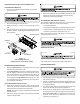
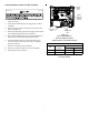
Pressure Switch
Hoses
Red/Blue
Yellow/Orange,
Electrical
Connections
Two-Stage
Pressure
Switch
Induced Draft
Blower
Figure 4
Induced Draft Blower
Pressure Switch Location
(Upflow shown, Counterflow similar)
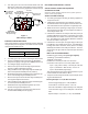
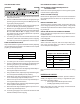
Low Stage High Stage
HAPS30 11177119 -0.15 -0.46
HAPS31 11177120 -0.15 -0.30
Set Point
7,001 - 11,000 ft.
Kit
Pressure
Switch
Table 7
Pressure Switch