
Installation Instructions


4
5. Turn OFF gas to the unit at the manual shutoff valve and
disconnect manometer. Reinstall line pressure tap plug.
Turn OFF any unnecessary appliances started in step 3.
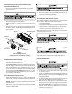
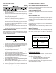
High Manifold
Regulator Adjustment
Screw (Under Cap)
Inlet Pressure Tap
(Side of Valve)
Low Manifold
Regulator Adjustment
Screw (Under Cap)
Outlet (Manifold)
Pressure Tap
(Side of Valve)
Gas Valve
ON/OFF Switch
Manometer
Hose
Figure 2
White-Rodgers 36E54
MANIFOLD PRESSURE CHECK
Only small variations in gas flow should be made by adjusting
the gas valve pressure regulator. See Table 4 for the required
natural gas manifold pressure.
Low Stage High Stage
1.6 to 2.2" w.c. 3.0 to 3.6" w.c.
Natural Gas Manifold Pressure
Table 4
1. Turn OFF gas to the unit at the manual gas shutoff valve.
2. Connect a calibrated water manometer or appropriate
gas pressure gauge at the gas valve outlet pressure tap.
3. Turn ON gas supply and operate unit.
4. Remove the cap screw from the high stage manifold
pressure regulator adjustment location.
5. Using an Allen wrench, adjust high stage manifold regu-
lator to the required manifold pressure (Table 4).
6. Reinstall the high stage manifold pressure regulator cap
screw. Confirm high stage manifold pressure.
7. Remove the cap screw from the low stage manifold pres-
sure regulator adjustment location.
8. Using an Allen wrench, adjust low stage manifold regula-
tor to the required manifold pressure.
9. Reinstall the low stage manifold regulator cap screw.
Confirm low stage manifold pressure.
10. Turn OFF gas supply to unit. Disconnect manometer
and reinstall manifold pressure tap plug.
UNIT OPERATION CHECKS - HANG16
CHECK NORMAL OPERATING SEQUENCE
OF IGNITION SYSTEM
Check the normal operating sequence of the ignition system to
ensure burners light properly.
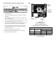
VERIFY GAS INPUT RATE(S)
1. Turn OFF gas supply to all other gas-burning appliances
except the furnace.
2. Install jumper wires between the R and W1 and the R
and W2 terminals of the integrated control module to ini-
tiate and maintain furnace operation on high stage heat.
3. While the furnace is operating on high stage, record the
time required (in seconds) for one complete revolution of
the small gas meter dial.
4. Calculate the number of seconds per cubic foot (sec/ft
3
) of
gas being delivered to the furnace. If the dial is a one-cubic
foot dial, divide the number of seconds recorded in step 3
by 1. If the dial is a two-cubic foot dial, divide the number of
seconds recorded in step 2 by 2.
5. Calculate the furnace input rate (high stage) in BTUs per
hour (Btu/hr). Input equals in the sum of: the installation’s
heating value and a conversion factor (hours to seconds)
divided by the number of seconds per cubic foot. The mea-
sured input must agree with the expected input calculated
in step 6.
INPUT CALCULATION EXAMPLE:
Installation’s gas heating value (from gas supplier)
1,000 Btu/ft
3
(at standard conditions)
720 Btu/ft
3
(at elevation)
Installation’s seconds per cubic foot: 30 sec/ft
3
Conversion Factor (hours to seconds): 3600 sec/hr
Input = (Htg. value x 3600) ÷ seconds per cubic foot
Input = (720 Btu/ft
3
x 3600 sec/hr) ÷ 30 sec/ ft
3
Input = 86,400 Btu/hr (high stage)
This measured input must agree with the derates for your
unit and altitude as indicated in Table 2.
6. Compare measured input rate with expected input result-
ing from altitude derate.
Derating Example 1: 11,500 BTU at 9,000 ft.
Sea level (high stage) input = 115,000 Btu/hr
From Table 2: Derate at 9,000 ft. = 24 ± 2%
Since this installation is approximately at the mid point
of the elevation range, use the mid point of the derate:
24%.
Expected Input = 115,000 x (1 - .24) = 87,400 Btu/hr