
Installation Instructions


3
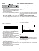
ORIFICE INSTALLATION - HANG16 AND HALP13
GAS MANIFOLD REMOVAL
1. Shut OFF gas supply at manual shutoff and turn OFF
power to the unit.
2. Disconnect wiring from the gas valve.
3. Where necessary, cut wire ties securing wiring to mani-
fold.
4. Remove the screws securing the gas manifold and valve to
the burner bracket. Separate gas manifold and valve from
burner bracket.
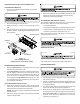
Burner Bracket
Burne
r
Manifold
Gas Valve
Ground wire
Figure 1
Gas Manifold Removal
(Upflow shown, counterflow similar)
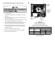
BURNER ORIFICE REPLACEMENT
1. Remove standard altitude natural gas orifices from gas
manifold using a box end wrench.
2. Install high altitude gas orifices supplied in the high alti-
tude kit. Tighten orifices with a box-end wrench; do not
use a socket wrench as it could damage the orifices; do
not cross-thread or overtighten. Refer to Tables 1 and 2
for the appropriate high altitude kit and orifice size. Ori-
fice usage depends on an installation’s gas usage (natu-
ral or propane) and altitude.
GAS MANIFOLD RE-INSTALLATION
1. Reinstall gas manifold and valve. Make certain that the
orifices are inserted in each burner and that each burner
remains properly seated in the burner bracket.
(NOTE: Secure green burner assembly ground wire with
manifold screw).
2. Reconnect wiring to gas valve. Secure wiring to manifold
using wire ties provided.
3. Refer to the following sections detailing Adjustments and
Checks for natural gas (HANG16) or Propane Spring
Change for propane gas (HALP13).
ADJUSTMENTS AND CHECKS - HANG16
The following adjustments and checks are a required part of
this ocnversion. Adjustment and checks include:
• Leak checking orifices
• Checking and adjusting line and manifold gas pressures
• Verfying proper unit operation (input rate, operational
sequence, burner flame, temperature rise, etc.)
Before proceeding, shut OFF gas supply at manual shut-off
and turn off power to the unit.
ORIFICE LEAK CHECK
Leak check burner orifice threads using a soap solution.
LINE PRESSURE CHECK
1. Shut OFF gas at the manual gas shutoff valve and turn
OFF power to the unit.
2. Connect a calibrated water manometer or appropriate gas
pressure gauge at either the gas valve inlet pressure tap
or gas piping drip leg.
3. Turn ON the power and gas, put the unit into heating cycle
and turn on all other gas consuming appliances.
4. Measure the gas supply pressure with the burners firing.
The inlet gas pressure for natural gas should be between
5.0 and 10.0 inches W.C. If supply pressure differs from
required, make necessary adjustments to pressure
regulator(s), gas piping, etc.