
Installation Instructions


6
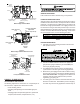
MANIFOLD PRESSURE CHECK
Only small variations in gas flow should be made by adjusting
the gas valve pressure regulator. See Table 5 for the required
natural gas manifold pressure.
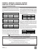
Manifold Gas Pressure
Natural Gas 3.5" w.c.
Propane Gas 10.0" w.c.
Table 5
1. Turn OFF gas to the unit at the manual gas shutoff valve.
2. Connect a calibrated water manometer or appropriate
gas pressure gauge at the gas valve outlet pressure tap.
3. Turn ON gas supply and operate unit.
4. Remove the cap screw from the manifold pressure regu-
lator adjustment location.
5. Adjust the manifold pressure regulator to the required
manifold pressure (Table 5).
6. Reinstall the manifold pressure regulator cap screw.
Confirm manifold pressure.
7. Turn OFF gas supply to unit. Disconnect manometer
and reinstall manifold pressure tap plug.
HANG 11, 12 and HALP10
UNIT OPERATION CHECKS - HANG11 AND 12
CHECK NORMAL OPERATING SEQUENCE
OF IGNITION SYSTEM
Check the normal operating sequence of the ignition system to
ensure burners light properly.
VERIFY GAS INPUT RATE(S)
1. Turn OFF gas supply to all other gas-burning appliances
except the furnace.
2. While the furnace is operating, record the time required (in
seconds) for one complete revolution of the small gas meter
dial.
3. Calculate the number of seconds per cubic foot (sec/ft
3
) of
gas being delivered to the furnace. If the dial is a one-
cubic foot dial, divide the number of seconds recorded in
step 2 by 1. If the dial is a two-cubic foot dial, divide the
number of seconds recorded in step 2 by 2.
4. Calculate the furnace input rate in BTUs per hour (Btu/hr).
Input equals in the sum of: the installation’s heating value
and a conversion factor (hours to seconds) divided by the
number of seconds per cubic foot. The measured input
must agree with the expected input calculated in step 5.
INPUT CALCULATION EXAMPLE:
Installation’s gas heating value (from gas supplier)
1,000 Btu/ft
3
(at standard conditions)
715 Btu/ft
3
(at elevation)
Installation’s seconds per cubic foot: 32 sec/ft
3
Conversion Factor (hours to seconds): 3600 sec/hr
Input = (Htg. value x 3600) ÷ seconds per cubic foot
Input = (715 Btu/ft
3
x 3600 sec/hr) ÷ 32 sec/ ft
3
Input = 80,438 Btu/hr
This measured input must agree with the derates for your
unit and altitude as indicated in Table 2.
5. Compare measured input rate with expected input result-
ing from altitude derate.
Derating Example 1: 11,500 BTU at 8000 ft.
Sea level (nameplate) input = 115,000 Btu/hr
From Table 2: Derate at 8000 ft. =15.3±4%
Since this installation is approximately at the mid point
of the elevation range, use the mid point of the derate:
15.3%.
Expected Input = 115,000 x (1 - .153) = 97,405 Btu/hr
Derating Example 2: 11,500 BTU at 7001 ft.
Sea level (nameplate) input = 115,000 Btu/hr
From Table 2: Derate at 7001 ft. = 15.3±4%
Since this installation is at the lower end of the elevation
range, use the lower derate:
(15.3 - 4) = 11.3%.
Expected Input = 115000 x (1 - .113) = 102,005 Btu/hr
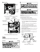
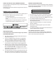
INSPECT BURNER FLAME
The burner flames should be stable, soft and blue (dust may
cause orange tips but they must not be yellow). They should
extend directly outward from the burners without curling, float-
ing, or lifting off.
Check the burner flames for:
1. Good adjustment
2. Stable, soft and blue
3. Not curling, floating, or lifting off.
Figure 8
Burner Flame