
Installation Instructions

5
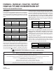
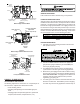
Pressure Regulator
Adjustment
(Under Cap Screw)
OUTLET
INLET
Gas Valve
On/Off
Control Knob
Inlet Pressure Tap
(Side of Valve)
Outlet (Manifold)
Pressure Tap
Figure 5
White-Rodgers Model 36E36
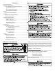
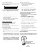
Pressure Regulator
Adjustment
(Under Cap Screw)
Gas Valve
On/Off
Selector
Switch
INLET
OUTLET
Inlet Pressure
Tap
Outlet Pressure
Tap
Figure 6
White-Rodgers Model 36G22 Gas Valve
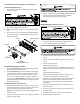
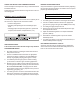
Honeywell
OFF
ON
OUTLET
INLET
Outlet (Manifold)
Pressure Tap
Pressure Regulator
Adjustment
(Under Cap Screw)
Inlet Pressure Tap
Gas Valve
On/Off
Control Knob
Figure 7
Honeywell VR8205 Gas Valve
HANG11, 12 AND HALP10
ADJUSTMENTS AND CHECKS
he following adjustments and checks are a required part of
this conversion. Adjustments and checks include:
• Leak checking orifices
• Checking and adjusting line and manifold gas pres-
sures
• Verifying proper unit operation (input rate, operational
sequence, burner flame, temperature rise, etc.)
etc.)
ORIFICE LEAK CHECK
Leak check burner orifice threads using a soap solution.
FURNACE OPERATION CHECK
Start the furnace using the procedures found in the furnace’s
installation instructions section, “Startup Procedures and Ad-
justments”. The line pressure supplied to the gas valve must
be within the range specified below. The supply pressure can
be measured at the gas valve inlet pressure tap or at a hose
fitting installed in the gas piping drip leg. The supply pressure
must be measured with the burners operating. To measure
the gas supply pressure, use the following procedure.
Propane Gas
Natural Gas
Inlet Gas Supply Pressure
Minimum:5.0" W.C. Maximum :10.0" W.C.
Minimum:11.0" W.C. Maximum :13.0" W.C.
Table 4
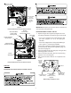
LINE PRESSURE CHECK
1. Shut OFF gas at the manual gas shutoff valve and turn
OFF power to the unit.
2. Connect a calibrated water manometer or appropriate
gas pressure gauge at either the gas valve inlet pres-
sure tap or gas piping drip leg.
3. Turn ON the power and gas, put the unit into heating
cycle and turn on all other gas consuming appliances.
4. Measure the gas supply pressure with the burners firing.
The inlet gas pressure for natural gas should be between
5.0 and 10.0 inches W.C. If supply pressure differs from
required, make necessary adjustments to pressure
regulator(s), gas piping, etc.
5. Turn OFF gas to the unit at the manual shutoff valve and
disconnect manometer. Reinstall line pressure tap plug.
Turn OFF any unnecessary appliances started in step 3.