
Installation Instructions

4
Mounting
Bracket
Screw
Induced Draft Blower
Two-Stage
Pressure Switch
Assembly
Pressure Switch
Hose
Induced
Draft
Blower
Yellow/Orange, Red/Blue
Electrical Connections
*
*
*
**
*
*
M1
2
3P
C
ON
O
F
F
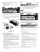
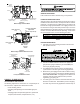
Figure 2
Induced Draft Blower Pressure Switch Location
Mounting
Bracket Screws
(Underneath Blower Deck)
Induced Draft Blower
Pressure Switch
Mounting Screws
Induced Draft Blower
Pressure Switch
Induced Draft
Blower
Yellow and Orange
Electrical Connections
Pressure
Switch Hose
Figure 3
Induced Draft Blower Pressure Switch Location
HALP10
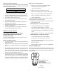
PROPANE GAS UNIT KIT INSTALLATION - HALP10
IMPORTANT: Propane gas is heavier than air and does not
vent upward as natural gas fuels.
PROPANE SPRING CHANGE - HALP10
1. Replace the gas valve regulator spring with one of the
new springs included in this propane gas conversion kit.
• If the unit is equipped with a White-Rodgers 36E
gas valve, (Figures 4, 5 or 6), use Spring Kit
#92-0659.
• If the unit is equipped with a Honeywell VR8205 gas
valve, (Figure 7), use Spring Kit #393691.
In each case, change the regulator spring per instruc-
tions included with that particular regulator spring. Dis-
card unused spring kits.
2. Attach the label (found in the spring kit) to the gas valve,
indicating propane conversion.
3. Attach conversion data plate, with correct input rating,
adjacent to the unit rating plate.
4. Post “conversion date certificate” on or adjacent to the
furnace.
O
F
F
ON
M
P
C
1
3
2
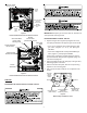
INLET
Pressure Regulator
Adjustment
(Under Cap Screw)
Inlet Pressure Tap
(Side of Valve)
Outlet (Manifold)
Pressure Tap
(Side of Valve)
Gas Valve
On/Off
Selector
Switch
OUTLET
Figure 4
White-Rodgers 36E22 Gas Valve