
Installation Instructions

3
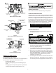
ORIFICE INSTALLATION-HANG11, 12 AND HALP10
GAS MANIFOLD REMOVAL
1. Shut OFF gas supply at manual shutoff and turn OFF
power to the unit.
2. Disconnect wiring from the gas valve.
3. Where necessary, cut wire ties securing wiring to mani-
fold.
4. Remove the screws securing the gas manifold and valve
to the burner bracket. Separate gas manifold and valve
from burner bracket.
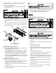
Burner Bracket
Burner
Manifold
Gas Valve
Figure 1
Gas Manifold Removal
BURNER ORIFICE REPLACEMENT
1. Remove standard altitude natural gas orifices from gas
manifold using a box end wrench.
2. Install high altitude gas orifices supplied in the high al-
titude kit. Tighten orifices with a box-end wrench; do not
use a socket wrench as it could damage the orifices;
do not cross-thread or overtighten. Refer to Table 1 for
the appropriate high altitude kit and orifice size. Orifice
usage depends on an installation’s gas usage (natural or
propane) and altitude.
GAS MANIFOLD RE-INSTALLATION
1. Reinstall gas manifold and valve. Make certain that the
orifices are inserted in each burner and that each burner
remains properly seated in the burner bracket.
(NOTE: Secure green burner assembly ground wire with
manifold screw).
2. Reconnect wiring to gas valve. Secure wiring to manifold
using wire ties provided.
3. Refer to the following sections detailing Adjustments and
Checks for natural gas (HANG11 & 12) or Propane
Spring Change for propane gas (HALP10).
HAPS27
PRESSURE SWITCH INSTALLATION
1. Shut off gas and disconnect power supply to furnace.
2. Locate the induced draft blower pressure
switch.
3. Disconnect the pressure switch hose from the pressure
switch.
4. Disconnect the yellow and orange wires from pressure
switch.
5. Remove pressure switch.
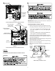
Upflow models (Figure 2):
Remove pressure switch mounting bracket screw secur-
ing pressure switch and mounting bracket to partition
panel.
Counterflow models (Figure 3):
Remove mounting bracket screws securing pressure
switch and mounting bracket to blower deck.
6. Remove screws from mounting bracket and transfer the
bracket to the HAPS27 pressure switch. Be sure to
maintain the same orientation as on the standard alti-
tude switch.
7. Install the HAPS27 pressure switch using screw(s) re-
moved in step 5.
8. Connect the yellow and orange wires to the HAPS 27
pressure switch.
9. Reconnect the pressure switch hose to new switch.
10. Verify proper furnace operation.