
GVZC20 Service Manual


SYSTEM OPERATION
9
This menu displays information about the systems current
status. This menu can be utilized to conrm correct func-
tionality of the equipment and for troubleshooting purposes.
The following items will be displayed:
• Heat Capacity Request Percentage
• Cool Capacity Request Percentage
• Heat Capacity Request During Defrost Percentage
• Dehumidication Request Percentage
• Reversing Valve Status
• Reported Airow by Indoor Unit
• Boost Mode
• Previous Defrost Run Time
The following sensor items will be displayed:
• Outdoor Temperature
• Coil Temperature
• Liquid Line Temperature
• Discharge Temperature
• Defrost Sensor
• Suction Pressure
This function can be enabled this menu.
Please follow the following sequence to enter PUMP
DOWN to accumulate the refrigerant to outdoor unit by 7
Segment Mode. Do not operate COOL ON or HEAT ON
mode to enter PUMP DOWN.
Before starting the PUMP DOWN operation, change indoor
fan trim, delay and prole back to default and stop elec-
tric heater and gas furnace. Remove if no trim feature. In
this operation, the gas and liquid service valve should be
opened.
1. Set 7-segment display to SCREEN 4 (SETTING MODE
2) Setting No. 8 and change the display from “-01” to
“-00” System will then automatically start PUMP DOWN
operation. For information on how to set 7-segment
display, see the section SETTING THE MODE DISPLAY
in this manual.
2. Approximately one minute later, the compressor should
start operating. Check the amperage at the compressor
wiring to see the compressor operation status. Unit dis-
play error code E11 (System verication Test) once the
PUMP DOWN operations starts.
3. Close liquid service valve approximately two minutes
after compressor has come on.
4. Compressor will come to a stop automatically. Close the
suction service valve immediately after the compressor
stops. After completion of PUMP DOWN, unit shows
error code“E11”.
NOTE: Refrigerant cannot be collected to the outdoor unit
completely if the system is overcharged or if there is a delay
in closing the liquid service valve and suction service valve.
Evacuate the left over refrigerant from the system using a
recovery machine.
The mandatory system verication test is enabled from this
menu, which enables a functional check of the equipment,
in addition to ensuring proper stop valve position.
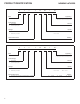
The system allows for the adjustment of several cooling
performance variables. Cool Airow Trim (*1), Cool Airow
Proles, Cool Fan ON Delay, Cool Fan OFF Delay and
Dehumidication Select (some enable option or o ) can be
adjusted in this menu. You can also reset this entire menu
to factory default settings.
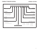
See the fol-lowing images showing the four cooling airow
proles.
• Prole A provides only an OFF delay of one (1) minute
at 100% of the cooling demand airow.
• Prole B ramps up to full cooling demand airow by
rst stepping up to 50% of the full demand for 30 sec-
onds. The motor then ramps to 100% of the required
airow. A one (1) minute OFF delay at 100% of the
cooling airow.
• Prole C ramps up to 82% of the full cooling demand
airow and operates there for approximately 7 1/2
minutes. The motor then steps up to the full demand
airow. Prole C also has a one (1) minute 100%
OFF delay.