
GVZC20 Service Manual

SYSTEM OPERATION
8
BOOST MODE can be enabled or disabled through the
control board push buttons or through the CoolCloud app.
BOOST MODE allows the system to operate at increased
compressor speed to satisfy unusual high loads. BOOST
MODE is initiated by an outdoor temperature sensor located
in the outdoor unit.
Please note that outdoor equipment operational sound
levels may increase while the equipment is running in
BOOST MODE. Disabling BOOST MODE will provide the
quietest and most ecient operation.
NOTE: BOOST MODE is applicable only for *VZC200**1AB
or later revision.
BOOST MODE is ON by default and is activated when the
outdoor temperature reaches 105°F. BOOST MODE can be
disabled and enabled and the activation temperature
adjusted in the Settings menu of the CoolCloud app or
through the indoor / outdoor push button menus.
If Installing with a CTK04 thermostat, please see the
addendum for further instructions.
The thermostat reads the indoor humidity level and allows
the user to set a dehumidication target based on these
settings. The thermostat controls the humidity level of the
conditioned space using the cooling system. Dehumidica-
tion is engaged whenever a cooling demand is present and
structural humidity levels are above the target level. When
this condition exists, the circulating fan output is reduced,
increasing system run time, over cooling the evaporator coil
and ultimately removing more humidity from the structure
than if only in cooling mode. The thermostat also allows for
an additional overcooling limit setting from 0°F to 3°F
setup. This allows the cooling system to further reduce
humidity by lowering the temperature up to 3°F below the
cooling setpoint in an attempt to better achieve desired
humidity levels.
For eective dehumidication operation:
• Ensure “Dehumidication” is not set to “OFF”
• Verify the cooling airow prole (cool proles) is set to
“Prole D”.
- See the Cool Set-up section of the InstallatioN
Manual for complete airow prole details.
- By default, “dehumidication selection” is stan-
dard and the cooling airow prole is set to
“ProleD”
• For additional dehumidication control, airow settings
are eld adjustable and can be ne-tuned to a value
that is comfortable for the application from a range of
Cool Airow Trim.
• In addition, the system can have Enhanced
Dehumidication operation in setting “A”, “B”, or “C” of
dehumidication based on dehumidication demand.
- See the Dehumidication Select section for more detail.
*The specication of *VZC200241AF, 0361AE,
0481AE, and 0601AE or earlier models are dierent
from this specication. For details, see the
Installation Manual or Service Manual that matches
the Major and Minor revision of the model name.
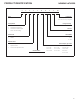
The ComfortBridge based inverter heating and air
conditioning system uses an indoor unit and outdoor unit
digitally communicating with one another via a two-way
communications path.
The 24 VAC single-stage thermostat sends commands to
the indoor and outdoor units.
The indoor and outdoor units interacting with one another
directly while taking simple analog commands from the
thermostat are the core of unlocking the benets and fea-
tures of the ComfortBridge control system.
NOTE: It is strongly recommend the use of thermostat with
humidity sensor and dehumidication terminal.
Without these functions, Dehumidication operation does
not work.
The ComfortBridge system permits access to additional
system information, advanced set-up features, and ad-
vanced diagnostic/troubleshooting features via the control
board push buttons or the CoolCloud mobile app.
(If using a CTK04 thermostat, please see the addendum for
further instructions.)
The heat pump’s diagnostics menu provides access to the
most recent faults. The six most recent faults can be ac-
cessed through the control board seven segment displays
or the CoolCloud mobile app. Any consecutively repeated
fault is stored a maximum of three times.
Example: A leak in the system, low refrigerant charge or an
incompletely open stop valve can cause the unit to ash
error code E15. This error code suggests that the unit is
experiencing operation at low pressure. The control will only
store this fault the rst three consecutive times the fault
occurs.
NOTE: The fault list can be cleared after performing
maintenance or servicing the system to assist in the
troubleshooting process.