
GVZC20 Service Manual


SERVICING
23
5. With the system still running, remove hose and reinstall
both valve caps.
6. Check system for leaks.
NOTE: Subcooling information is valid only while the unit is
operating at 100% capacity or 100% of compressor speed
in CHARGE MODE. Compressor speed is displayed under
STATUS menu in the thermostat.
The reason for compressor ineciency is that the com-
pressor is broken or damaged, reducing the ability of the
compressor to pump refrigerant vapor.
The condition of the compressor is checked in the following
manner.
1. Attach gauges to the high and low side of the system.
2. Start the system and run CHARGE MODE.
If the test shows:
a. Below normal high side pressure.
b. Above normal low side pressure.
c. Low temperature dierence across coil.
d. Low amp draw at compressor.
And the charge is correct. The compressor is faulty - re-
place the compressor.
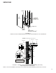
The expansion valve is designed to control the rate of liquid
refrigerant ow into an evaporator coil in exact proportion
to the rate of evaporation of the refrigerant in the coil. The
amount of refrigerant entering the coil is regulated since the
valve responds to temperature of the refrigerant gas leaving
the coil (feeler bulb contact) and the pressure of the refrig-
erant in the coil. This regulation of the ow prevents the
return of liquid refrigerant to the compressor.
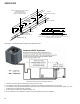
Some TXV valves contain an internal check valve thus
eliminating the need for an external check valve and bypass
loop. The three forces which govern the operation of the
valve are: (1) the pressure created in the power assem-
bly by the feeler bulb, (2) evaporator pressure, and (3) the
equivalent pressure of the superheat spring in the valve.
0% bleed type expansion valves are used on indoor and
outdoor coils. The 0% bleed valve will not allow the system
pressures (High and Low side) to equalize during the shut
down period. The valve will shut o completely at approxi-
mately 100 PSIG.
30% bleed valves used on some other models will continue
to allow some equalization even though the valve has shut-
o completely because of the bleed holes within the valve.
This type of valve should not be used as a replacement for
a 0% bleed valve, due to the resulting drop in performance.
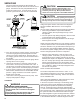
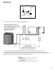
The bulb must be securely fastened with two straps to a
clean straight section of the suction line. Application of
the bulb to a horizontal run of line is preferred. If a vertical
installation cannot be avoided, the bulb must be mounted
so that the capillary tubing comes out at the top.
THE VALVES PROVIDED BY THE MANUFACTURER ARE
DESIGNED TO MEET THE SPECIFICATION REQUIRE-
MENTS FOR OPTIMUM PRODUCT OPERATION. DO
NOT USE SUBSTITUTES.
Overfeeding by the thermostatic expansion valve results in
high suction pressure, cold suction line, and possible liquid
slugging of the compressor.
If these symptoms are observed:
1. Check for an overcharged unit by referring to the cooling
performance charts in the servicing section.
2. Check the operation of the power element in the valve
as explained in Checking Thermostatic Expansion Valve
3. Check for restricted or plugged equalizer tube.
Underfeeding by the thermostatic expansion valve results
in low system capacity and low suction pressures.
If these symptoms are observed:
1. Check for a restricted liquid line or drier. A restriction will
be indicated by a temperature drop across the drier.
2. Check the operation of the power element of the valve
as described in Checking Thermostatic Expansion Valve
Operation.
The thermostatic expansion valve is factory adjusted to
maintain 8°F ± 1°F degrees superheat of the suction gas.
Before checking the superheat or replacing the valve,
perform all the procedures outlined under Air Flow, Refrig-
erant Charge, Thermostatic Expansion Valve - Overfeeding,
Underfeeding. These are the most common causes for
evaporator malfunction.
CHECKING SUPERHEAT
Refrigerant gas is considered superheated when its tem-
perature is higher than the saturation temperature corre-
sponding to its pressure. The degree of superheat equals
the degrees of temperature increase above the saturation
temperature at existing pressure. See Temperature - Pres-
sure Chart on following pages.
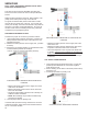
1. Run system at least 10 minutes to allow pressure to
stabilize.
2. For best results, temporarily install a thermometer on the
liquid line at the liquid line service valve and 4-6” from
the compressor on the suction line. Ensure the thermom-
eter makes adequate contact and is insulated for best
possible readings. Use liquid line temperature to deter-
mine sub-cooling and vapor temperature to determine
superheat.