
GVZC20 Service Manual


SERVICING
20
MOTOR CONTROL CIRCUITS
1. Turn on power to air handler or modular.
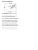
2. Check voltage between pins 1 and 4 at the 4-wire motor
connector on the control board. Voltage should be be-
tween 9 and 15 VDC. Replace control if voltage is not as
specied.
ELECTRIC HEAT SEQUENCER OUTPUTS
1. Turn on power to air handler or modular blower.
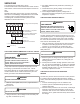
2. Disconnect the 3-circuit harness connecting the control to
the electric heater kit.
3. Provide a thermostat demand for low stage auxiliary heat
(W1). Measure the voltage between pins 1 and 3 at the
on-board electric heat connector. Voltage should mea-
sure 24VAC. Replace control if no voltage is present.
NOTE: Allow for any built-in time delays before making
voltage measurements. Any electric heater faults that are
present may prevent the heater output from energizing.
Verify that no heater faults are present before making volt-
age measurements.
COMMUNICATIONS
The integrated air handler control has some on-board tools
that may be used to troubleshoot the network. These tools
are: red communications LED, green receive (Rx) LED, and
learn button. These are described below
a. Red communications LED – Indicates the status of the
network. Refer to the Network Troubleshooting Chart for
the LED status and the corresponding potential problem.
b. Green receive LED – Indicates network trac. Refer to
the Network Troubleshooting Chart for the LED status
and the corresponding potential problem.
c. Learn button – Used to reset the network. Depress the
button for approximately 2 seconds to reset the network.
For detail see NETWORK TROUBLESHOOTING section.
When repairing the refrigeration system:
1. Never open a system that is under vacuum. Air and
moisture will be drawn in.
2. Plug or cap all openings.
3. Remove all burrs and clean the brazing surfaces of the
tubing with sand cloth or paper. Brazing materials do not
ow well on oxidized or oily surfaces.
4. Clean the inside of all new tubing to remove oils and
pipe chips.
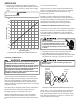
5. When brazing, sweep the tubing with dry nitrogen to
prevent the formation of oxides on the inside surfaces.
6. Complete any repair by replacing the liquid line drier in
the system, evacuate and charge.
BRAZING MATERIALS
Important note: Torch heat required to braze tubes of
various sizes is proportional to the size of the tube. Tubes
of smaller size require less heat to bring the tube to braz-
ing temperature before adding brazing alloy. Applying too
much heat to any tube can melt the tube. Service personnel
must use the appropriate heat level for the size of the tube
being brazed.
NOTE: The use of a heat shield when brazing is recom-
mended to avoid burning the serial plate or the nish on the
unit. Heat trap or wet rags should be used to protect heat
sensitive components such as stop valves, EEV, TXV and
lters.
Copper to Copper Joints - Sil-Fos used without ux (alloy