
GVZC20 Service Manual


SERVICING
19
TROUBLESHOOTING
MOTOR CONTROL CIRCUITS
1. Turn on power to air handler or modular.
2. Check voltage between pins 1 and 4 at the 4-wire motor
connector on the control board. Voltage should be
between 9 and 15 VDC. Replace control if voltage is not
as specied.
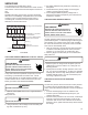
ELECTRIC HEAT SEQUENCER OUTPUTS
1. Turn on power to air handler or modular blower.
2. Disconnect the 4-circuit harness connecting the control to
the electric heater kit.
3. Provide a thermostat demand for low stage auxiliary
heat. Measure the voltage between pins 1 and 3 at the
onboard electric heat connector. Voltage should mea-
sure 24VAC. Replace control if no voltage is present.
NOTE: Allow for any built-in time delays before making
voltage measurements. Any electric heater faults that are
present may prevent the heater output from energizing. Ver-
ify that no heater faults are present before making voltage
measurements.
4. Provide a thermostat demand for high stage auxiliary
heat (W1 + W2). Measure the voltage between pins 1
and 3 at the on-board electric heat connector. Measure
the voltage between pins 2 and 3 at the on-board electric
heat connector. Voltage should measure 24VAC. Re-
place control if no voltage is present.
Communications (Applies only to Systems with Compatible
ComfortNetTM Outdoor Unit and CTK04AE* Thermostat)
The integrated air handler control has some on-board tools
that may be used to troubleshoot the network. These tools
are: red communications LED, green receive (Rx) LED, and
learn button. These are described below
a. Red communications LED – Indicates the status of the
network. Refer to the Network Troubleshooting Chart for
the LED status and the corresponding potential problem.
b. Green receive LED – Indicates network trac. Refer to
the Network Troubleshooting Chart for the LED status
and the corresponding potential problem.
c. Learn button – Used to reset the network. Depress the
button for approximately 2 seconds to reset the network.
For details, see NETWORK TROUBLSHOOTING section.
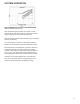
DESCRIPTION
The AVPEC* models utilize an electronic control that pro-
vides ECM blower motor control and control of up to two
electric heat sequencers. The control has thermostat inputs
for variable stage of cooling/heating, two stages of electric
heat, reversing valve, and dehumidication. Control input is
24 VAC.
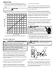
FEATURES
The new air handler control includes advanced diagnostic
features with fault recall, estimated CFM display via 7
segment display of control boad, CoolCloud
TM
and
ComfortNet
TM
ready. Diagnostics includes heater kit selec-
tion diagnostics, open fuse, internal control fault, data er-
rors, and blower motor faults. Data errors are not included
in the fault recall list. Diagnostic error codes are displayed
on a single red LED. The estimated CFM is displayed on
an on-board 7 segment display. For example, if the CFM is
1240CFM, 7 segment display shows “FC...A...12...40...”.
The AVPEC* air handlers may be used in a fully communi-
cating system when matched with a compatible outdoor unit
and the thermostat. A fully communicating system oers
advanced setup and diagnostic features.
BASIC OPERATION
The air handler control receives operation demand inputs
from the thermostat. The control operates the variable
speed blower motor at the demand as determined from the
thermostat input(s). If a demand for electric heat is re-
ceived, the control will provide a 24VAC output for up to two
electric heat sequencers.
TROUBLESHOOTING