
GVZC20 Service Manual


SERVICING
16
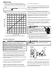
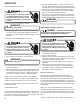
4. Compare your readings to the detected pressure vs
output voltage in the following table. Replace the sensor
if the sensor is open, shorted, or outside of the voltage
range.
L
INE
V
OLTAGE
NOW
PRESENT
.
-200
-100
0
100
200
300
400
500
600
700
800
0.0 0.5 1.0 1.5 2.0 2.5 3.0 3.5 4.0
Detected Pressure (PSIG)
Output Voltage (DCV)
VOLTAGE AND PRESSURE CHARACTERISTICS
If the compressor terminal PROTECTIVE COVER and
gasket (if required) are not properly in place and secured,
there is a remote possibility if a terminal vents, that the
vaporous and liquid discharge can be ignited, spouting
ames several feet, causing potentially severe or fatal injury
to anyone in its path.
This discharge can be ignited external to the compressor if
the terminal cover is not properly in place and if the
discharge impinges on a sucient heat source.
Ignition of the discharge can also occur at the venting
terminal or inside the compressor, if there is sucient
contaminant air present in the system and an electrical arc
occurs as the terminal vents.
Ignition cannot occur at the venting terminal without the
presence of contaminant air, and cannot occur externally
from the venting terminal without the presence of an
external ignition source.
Therefore, proper evacuation of a hermetic system is
essential at the time of manufacture and during servicing.
To reduce the possibility of external ignition, all open ame,
electrical power, and other heat sources should be
extinguished or turned o prior to servicing a system.
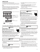
The Inverter on the outdoor control board takes the position
signal from the UVW line, connected with the compressor.
If the system detects a malfunction on the compressor,
check the insulation resistance in accordance with the fol-
lowing procedure.
1. Remove the leads from the compressor terminals.
2. Using a Megometer, attach one lead to ground.
3. Using the other lead of the Megometer, check the insula-
tion between U to ground, V to ground, W to ground.
Compressor
Terminal
Unpainted
Refrigerant
Piping
TESTING COMPRESSOR WINDINGS INSULATION
NOTE: The 2, 3, and 4 ton compressor has a terminal on
the top. The 5 ton compressor has the terminals on the
side. If the insulation resistance of the compressor is less
than 100k Ohms between U to ground, V to ground, W to
ground, replace the compressor.