
GVZC20 Service Manual


SERVICING
14
1. Remove outer case, control panel cover, etc., from unit
being tested.
With power ON:
L
INE
V
OLTAGE
NOW
PRESENT
.
2. Using a voltmeter, measure the voltage across terminals
L1 and L2 of the contactor for the heat pump condens-
er unit or at the eld connections for the air handler or
heaters.
Measure the voltage across the L1 and L2 lugs on the
unitary (UC) control.
3. No reading - indicates open wiring, open fuse(s) no pow-
er or etc., from unit to fused disconnect service. Repair
as needed.
4. With ample voltage at line voltage connectors, energize
the unit.
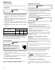
voltage min. max.
Outdoor Unit, Air Handler,
Modular Blower, Heater Kit
208/230 197 253
Gas Furnaces
115 103 126
Unit Supply Voltage (VAC)
Unit Type
NOTE: When operating electric heaters on voltages other
than 240 volt, refer to the System Operation section on
electric heaters to calculate temperature rise and air ow.
Low voltage may cause insucient heating.
HIGH VOLTAGE !
DISCONNECT ALL POWER BEFORE SERVICING OR
INSTALLING. MULTIPLE POWER SOURCES MAY BE
PRESENT. FAILURE TO DO SO MAY CAUSE PROPERTY
DAMAGE, PERSONAL INJURY OR DEATH.
1. Check wiring visually for signs of overheating, damaged
insulation and loose connections.
2. Use an ohmmeter to check continuity of any suspected
open wires.
3. If any wires must be replaced, replace with comparable
gauge and insulation thickness.
Communicating Thermostat Wiring: The maximum wire
length for 18 AWG thermostat wire is 250 feet.
L
INE
V
OLTAGE
NOW
PRESENT
.
With power ON, thermostat calling for cooling/heating.
1. Use a voltmeter to check for 24 volt at thermostat wires
C and R in the indoor unit control panel.
2. No voltage indicates trouble in the thermostat, wiring or
transformer source.
3. Check the continuity of the thermostat and wiring. Re-
pair or replace as necessary.
L
INE
V
OLTAGE
NOW
PRESENT
.
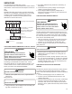
Resistance Heaters
With power ON:
1. Set room thermostat to a higher setting than room
temperature so both stages call for heat.
2. With voltmeter, check for 24 volt at each heater relay.
3. No voltage indicates the trouble is in the thermostat or
wiring.
4. Check the continuity of the thermostat and wiring.
Repair or replace as necessary.
NOTE: Consideration must be given to how the heaters
are wired (O.D.T. and etc.). Also safety devices must be
checked for continuity.
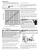
OVERVIEW
The ComfortBridge based inverter heating and air
conditioning system uses an indoor unit and outdoor unit
digitally communicating with one another via a two-way
communications path.
The 24 VAC single-stage thermostat sends commands to
the indoor and outdoor units.
The indoor and outdoor units interacting with one another
directly while taking simple analog commands from the
thermostat are the core of unlocking the benets and
features of the ComfortBridge control system.
NOTE:
It is recommend the use of thermostat with
humidity sensor and dehumidication terminal.
Without these functions, Dehumidication operation does
not work.
ComfortBridge™ control system is low voltage wiring
consists of two wires between the indoor unit and outdoor
unit.