
GVZC20 Service Manual


ACCESSORIES
117
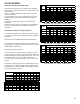
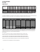
For installations not indicated above the following formula is
to be used:
TR = (kW x 3412) x (Voltage Correction) / (1.08 x CFM)
Where: TR = Temperature Rise
kW = Heater Kit Actual kW
3412 = Btu per kW
VC* = 1.0 (240 Supply Volts)
= 0.92 (230 Supply Volts)
= 0.84 (220 Supply Volts)
= 0.77 (210 Supply Volts)
= 0.75 (208 Supply Volts)
1.08 = Constant
CFM = Measured Airow
*VC (Voltage Correction)
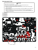
Each individual heater element is protected with a limit con-
trol device connected in series with each element to prevent
overheating of components in case of low airow. This limit
control will open its circuit at approximately 150°F to 160°F
and close at approximately 110°F.
1. Remove the wiring from the control terminals.
2. Using an ohmmeter, test for continuity across the nor-
mally closed contacts. No reading indicates the control is
open - replace if necessary.
IF FOUND OPEN - REPLACE - DO NOT WIRE AROUND.
Each individual heater element is protected with a one time
fuse link which is connected in series with the element. The
fuse link will open at approximately 333°.
1. Remove heater element assembly so as to expose fuse
link.
2. Using an ohmmeter, test across the fuse link for conti-
nuity - no reading indicates the link is open. Replace as
necessary.
NOTE: The link is designed to open at approximately
333°F. DO NOT WIRE AROUND - determine reason for
failure.