
GVZC20 Service Manual


TROUBLESHOOTING
107
HIGH VOLTAGE !
DISCONNECT ALL POWER BEFORE SERVICING OR
INSTALLING. MULTIPLE POWER SOURCES MAY BE
PRESENT. FAILURE TO DO SO MAY CAUSE PROPERTY
DAMAGE, PERSONAL INJURY OR DEATH.
W
HEN
REPLACING
THE
ELECTRICAL
BOARD
,
DO
NOT
TOUCH
THE
HATCHED
AREAS
. B
EFORE
INSTALLING
THE
NEW
ELECTRICAL
BOARD
,
BE
SURE
TO
WIPE
THE
GREASE
OFF
THE
REFRIGERANT
TUBING
. E
XERCISE
CAUTION
TO
NOT
DAMAGE
THE
ELECTRICAL
CONNECTIONS
.
D
ISCONNECT
AS
NEEDED
.
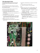
When uninstalling the main electrical board, remove the
screws holding the cover in place. If board replacement is
attempted without following proper uninstallation procedure,
the refrigerant piping might be damaged. Always replace
the grease with new grease on heat sink used for cooling.
Not replacing grease may result in insucient cooling and
may damage the electrical board.
1. Remove the xing screw A.
2. Lift the cover and open it in the direction shown in the
gure.
3. Remove xing screws B axing the sheet metal plate.
4. Carefully slide the sheet metal plate with the electrical
board behind the refrigerant tubing as shown.
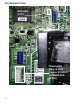
Use the grease that
is provided with the
service parts
.20
.20
Make sure
that you are
coating
evenly
Cover
Heat sink for cooling
Fixing
screw A
Refrigerant Tubing
Fixing screws B
screw A
Nail
Nail
Tighten torque:
14.1±1.7 lbf-in
Tighten with a driver until
the position where a
tightening torque increases
suddenly.
Then extra-tighten by
30° to 40°
When working on a service port, ensure that no refrigerant
and/or compressor oil is sprayed onto the electrical board.
This could damage the board’s functionality.
1. Wipe the stale grease completely from the installed pip-
ing. If you reinstall the control board, make sure to wipe
clean the heat sink on the board. Coat the surface with
the standard quantity of the specied new grease.
2. Carefully slide the sheet metal plate back in and x the
screws B.
3. Do not apply force to the parts on the control board. Hold
the control board plate NOT the control board.
4. Ensure that the liquid tube does not come in contact with
any part of the PCB assembly.
5. Gently t the tube in the heat sink troughs. Ensure good
contact.
6. Close the cover, slide it downwards, x it with the nails
(two nails) and tighten xing screws A so that the piping
is tightly connected.