
GVZC20 Installation Manual


52
A ComfortNet inverter heating and air conditioning system
uses an indoor unit, outdoor unit and thermostat which
digitally communicate with one another via a two-way
communications path. The thermostat sends commands to
the indoor and outdoor units. The thermostat may request
and receive information from both the indoor and outdoor
units. This information may be displayed on the CTK04
thermostat. The indoor and outdoor units also interact
with one another. The outdoor unit may send commands
to or request information from the indoor unit. This two-
way digital communications between the thermostat and
subsystems (indoor/outdoor unit) and between subsystems
is the key to unlocking the benets and features of the
ComfortNet system.
Two-way digital communications is accomplished using
only two wires. The thermostat needs 24 VAC for power.
4 wires between the indoor unit and thermostat plus two
wires between the indoor unit and outdoor unit are all that
are required to operate the system.
The ComfortNet™ system permits access to additional
system information, advanced set-up features, and
advanced diagnostic/troubleshooting features. These
advanced features are organized into a menu structure.
See the HEAT PUMP ADVANCED FEATURES MENU
section for the menu layout.
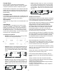
Press MENU, scroll down and press COMFORTNET USER
MENU. Enter the date code (password) when prompted.
The date code is printed on the back of the thermostat; or
press MENU > EQUIPMENT STATUS and scroll down to
nd the date code. After you enter the password, select
COMFORTNET USER MENU, answer YES to the following
menu and select HEAT PUMP to view the system menus.
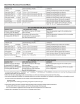
The heat pump’s diagnostics menu provides access to the
most recent faults. The six most recent faults are displayed
on the rst screen. Six additional faults are displayed
under fault history. Faults are stored in order from most
recent to least recent. Any consecutively repeated fault is
stored a maximum of three times. Example: A leak in the
system, low refrigerant charge or an incompletely open
stop valve can cause the unit to ash error code E15. This
error code suggests that the unit is experiencing operation
at low pressure. The control will only store this fault the rst
three consecutive times the fault occurs.
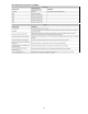
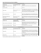
This menu displays information about the systems current
status. This menu can be utilized to conrm correct
functionality of the equipment and for troubleshooting
purposes. The following items will be displayed:
TS Ti me Stamp
MD Mode
CRM Compressor Reduction Mode
RAD Requested and Actual % Demand
RAF Requested and Reported ID CFM
ATOF*
Outdoor Air Temperature and Outdoor Fan RPM
DCT
Discharge Temperature and Outdoor Coil Temperature
DLT
Defrost Sensor and Outdoor Liquid Temperature
PSDST**
Pressure Sensor and Outdoor Suction Temperature
and
GVZC20**AA
Provides compressor run time in hours.
Mode: Current system operational mode (COOLING,
HEATING, COOLING STARTUP, HEATING STARTUP, OIL
RETURN, DEFROST, STOP).
The compressor is running
at a speed lower than what is requested, based on the cool-
ing load.
Compares the request-
ed cooling demand to what the equipment is providing. For
steady state operation, these numbers should match.
Compares the requested
indoor airow to what the indoor equipment has reported.
Displays
the outdoor air temperature as well as the outdoor fan speed
(RPM).
Displays the discharge temperature and outdoor coil tem-
perature sensor readings.
Dis-
plays defrost sensor and outdoor liquid temperature sensor
readings.
Displays the pressure sensor reading.
In order to properly return oil to
the compressor, compressor speed may periodically adjust
to assist oil circulation.