
GVZC20 Installation Manual


29
If a network communication error code has occurred, use
the following steps to help troubleshoot the system. (For
network communication error codes, refer to the table
below and the tables of error codes for outdoor unit and
indoor unit.)
After any wiring changes have been made or DS1 dip
switches on the outdoor unit control board have been
changed, apply power to the system and see if the error
codes have cleared.
1. Conrm low voltage wiring is correct per installation
instructions. Check for miswiring. (i.e. Terminal 1 and
2 is reversed.)
2. Check wires for damage. (i.e. Broken wire at terminal,
broken inside wire nuts or damaged cable between
units.)
3. Perform continuity check on wires to make sure cable
is OK. Replace the cable if necessary.
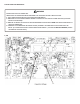
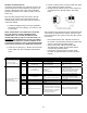
4. Change both dip switches of DS1 on the outdoor unit
control board to the opposite position. See image
below.
The integrated control module has some onboard tools that
can be used to troubleshoot the network. These tools are:
red communications LED, green receive (Rx) LED, and the
Learn button.
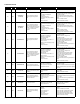
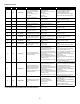
• Red communications LED - Indicates the status of
the network. The table below indicates the LED status
and the corresponding potential problem.
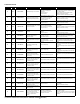
• Green receive LED - Indicates network trac.
The table below indicates the LED status and the
corresponding potential problem.
• Learn button - Used to reset the network. Press
the button for approximately 5 seconds to reset the
network.
Off Normal Condition
• None • None
1 Flash Communications Failure
• Unknown packet is received
• Communications failure
• Depress Learn button
• Verify wiring connection
2 Flash Out-of-box reset
• Control power up
• Learn button depressed
• None
Off
No power
Communications error
• No power to unit
• Open fuse
• Communication error
• Check circuit breakers and fuses;
Reset/Replace if needed
• Reset network by depressing Learn button
• Check communication wires (Terminal
1/Terminal 2 wires); Replace if needed
• Check for shorts in low voltage wiring.
1 Steady
Flash
No network found
• Broken/disconnected communication
wire(s)
• Unit is installed as a legacy/traditional
system
• Check communication wires (Terminal
1/Terminal 2 wires); Replace if needed
• Check installation type (legacy/traditional or
communicating)
Rapid Flashing Normal network traffic
• Control is "talking" on network as
expected
• None
On Solid Terminal 1/Terminal 2 mis-wire
• Terminal 1 and Terminal 2 wires reversed
at indoor unit, thermostat, or outdoor unit
• Short between Terminal 1 and Terminal 2
wires
• Short between Terminal 1 or Terminal 2
two wires and Terminal C (24VAC) or
Terminal R (24VAC, COM)
• Check communication wires (Terminal
1/Terminal 2 wires); Replace if needed
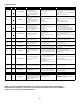
Red Communications LED Outdoor
unit control board: (H1P)
Indoor unit control board: (H2P)
Green Receive LED Outdoor unit
control board: (H2P)
Indoor unit control board: (H3P)