
GSZC18 Installation

9
System
System Operating
Mode
Airflow
Demand Source
Cooling Heat Pump
Heat Pump Heating
Only
Heat Pump
HP + Electric Heat
Strips
> of Heat Pump or Air
Handler Demand
Electric Heat Strips
Only
Air Handler
Continuous Fan Thermostat
Cooling Heat Pump
Heat Pump Heating
Only
Heat Pump
Auxiliary Heating Furnace
Continuous Fan Thermostat
Heat Pump + Air
Handler
Heat Pump +
Furnace
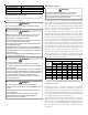
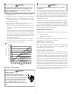
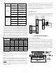
For example, assume the system is a heat pump matched with an
air handler. With a call for low stage cooling, the heat pump will
calculate the system’s low stage cooling airflow demand. The
heat pump will then send a fan request along with the low stage
cooling airflow demand to the air handler. Once received, the air
handler will send the low stage cooling airflow demand to the
ECM motor. The ECM motor then delivers the low stage cooling
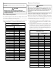
airflow. The table at right lists the nominal high and low stage
airflow for the ComfortNet™ heat pumps.
High Low High Low
*SZC160241 800 600 800 600
*SZC160361 1200 800 1200 800
*SZC160481 1550 1100 1550 1100
*SZC160601 1800 1210 1800 1210
*SZC180241 850 550 850 550
*SZC180361 1250 850 1250 850
*SZC180481 1550 1210 1550 1210
*SZC180601 1750 1210 1750 1210
Models
Cooling Heating
CONTROL W IRING
NOTE: Refer to section Electrical Connections - High Voltage
Connections for 208/230 volt line connections to the air
conditioner or heat pump.
NOTE: A removable plug connector is provided with the control
board to make thermostat wire connections. This plug may be
removed, wire connections made to the plug, and replaced. It is
strongly recommended that you do not connect multiple wires
into a single terminal. Wire nuts are recommended to ensure
one wire is used for each terminal. Failure to do so may result in
intermittent operation.
Typical 18 AWG thermostat wire may be used to wire the system
components. However, communications reliability may be im-
proved by using a high quality, shielded, twisted pair cable for
the data transmission lines. In either case, 150 feet is the maxi-
mum length of wire between indoor unit and outdoor unit, or
between indoor unit and thermostat.
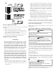
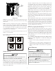
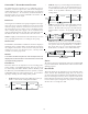
TWO-WIRE OUTDOOR
For communicating systems, only two wires are required between
the indoor and outdoor units. This wiring scheme requires only
the data lines, 1 and 2 between indoor and outdoor equipment.
R
C
G
Y
Optional
Optional
Optional if
feature
supported by
thermostat
INDOOR
BOARD TERMINAL
CONNECTIONS
OUTDOOR
BOARD TERMINAL
CONNECTIONS
OUTDOOR
TRANSFORMER
1
2
C
R
C
G
Y
1
2
C
System Wiring using Two-Wires
between indoor and outdoor equipment
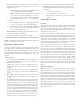
LEGACY CONTROLS WIRING
The intergrated control board on this unit is factory-equipped
with a 4-pin connector for low voltage contols wiring for com-
municating systems. If the system is installed as a non-commu-
nicating (legacy) system, remove the 4-pin connector and dis-
connect the transformer low voltage and line voltage wiring.
Then, install the 7-pin connector that is supplied in the litera-
ture/accessories bag into the intergrated control board in the
appropriate location indicated by the color-coded labels found
on both the control board and pin connector plug.
RCG O
RCG O
RCG O
12
System Wiring for legacy controls