
GSZC18 Installation

6
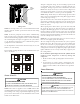
HIGH
VOLTAGE
PORT
LOW
VOLTAGE
PORT
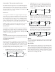
Voltage Ports
NOTE: For two-stage units, refer to the Installation Instructions
supplied with the variable speed indoor units for field wiring
connections.
NOTE: If the heat pump unit is wired in the communicating
mode together with a compatible communicating indoor unit,
then the communicating equipment is able to search and identify
the condensing unit when power is applied to the system. Refer
to the Installation Manual of the communicating indoor
equipment for more information.
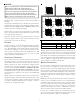
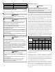
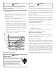
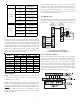
Use the dipswitch to select defrost time interval (30, 60, 90, 120
minutes; see chart below).
Factory default setting is 30 minutes. The maximum defrost cycle
time is 10 minutes.
60
30
0
30 Minutes
60
60
30
0
60 Minutes
60
120 Minutes
60
30
0
90 Minutes
60
60
30
0
60
Dipswitch Settings for Selection of Defrost Time
S
YSTEM
S
TART
U
P
POSSIBLE REFRIGERANT LEAK!
T
O
AVOID
A
POSSIBLE
REFRIGERANT
LEAK
,
OPEN
THE
SERVICE
VALVES
UNTIL
THE
TOP
OF
THE
STEM
IS
1/8”
FROM
THE
RETAINER
.
CAUTION
NOTE: Power must be supplied to the 18 SEER outdoor units
containing ECM motors before the power is applied to the indoor
unit. Sending a low voltage signal without high voltage power
present at the outdoor unit can cause malfunction of the control
module on the ECM motor.
Adequate refrigerant charge for the matching evaporator coil
or air handler and 15 feet of lineset is supplied with the con-
densing unit. If using evaporator coils or air handlers other than
HSVTC coil it maybe necessary to add or remove refrigerant to
attain proper charge. If line set exceeds 15 feet in length, refrig-
erant should be added at .6 ounces per foot of liquid line.
NOTE: Charge should always be checked using superheat when
using a piston and subcooling when using TXV equipped indoor
coil to verify proper charge.
Open the suction service valve first! If the liquid service valve is
opened first, oil from the compressor may be drawn into the
indoor coil TXV, restricting refrigerant flow and affecting opera-
tion of the system.
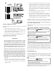
When opening valves with retainers, open each valve only until
the top of the stem is 1/8” from the retainer. To avoid loss of
refrigerant, DO NOT apply pressure to the retainer. When open-
ing valves without a retainer remove service valve cap and insert
a hex wrench into the valve stem and back out the stem by turn-
ing the hex wrench counterclockwise. Open the valve until it con-
tacts the rolled lip of the valve body.
NOTE: These are not back-seating valves. It is not necessary to
force the stem tightly against the rolled lip.
After the refrigerant charge has bled into the system, open the
liquid service valve. The service valve cap is the secondary seal
for the valve and must be properly tightened to prevent leaks.
Make sure cap is clean and apply refrigerant oil to threads and
sealing surface on inside of cap. Tighten cap finger-tight and then
tighten additional 1/6 of a turn (1 wrench flat) to properly seat
the sealing surfaces.
Do not introduce liquid refrigerant from the cylinder into the
crankcase of the compressor as this may damage the
compressor.
1. Break vacuum by fully opening liquid and suction base
valves.
2. Set thermostat to call for cooling. Check indoor and
outdoor fan operation and allow system to stabilize for 10
minutes for fixed orifices and 20 minutes for expansion
valves.
C
HARGE
V
ERIFICATION
REFRIGERANT UNDER PRESSURE!
• D
O
NOT
OVERCHARGE
SYSTEM
WITH
REFRIGERANT
.
• D
O
NOT
OPERATE
UNIT
IN
A
VACUUM
OR
AT
NEGATIVE
PRESSURE
.
F
AILURE
TO
FOLLOW
PROPER
PROCEDURES
MAY
CAUSE
PROPERTY
DAMAGE
,
PERSONAL
INJURY
OR
DEATH
.
WARNING
U
SE
REFRIGERANT
CERTIFIED
TO
AHRI
STANDARDS
. U
SED
REFRIGERANT
MAY
CAUSE
COMPRESSOR
DAMAGE
,
AND
DAMAGE
CAUSED
BY
USED
REGRIGERANT
IS
NOT
COVERED
UNDER
THE
WARRANTY
. M
OST
PORTABLE
MACHINES
CANNOT
CLEAN
USED
REFRIGERANT
TO
MEET
AHRI
STANDARDS
.
CAUTION