
GSZC18 Installation

5
P
ROLONGED
OPERATION
AT
SUCTION
PRESSURES
LESS
THAN
20
PSIG
FOR
MORE
THAN
5
SECONDS
WILL
RESULT
IN
OVERHEATING
OF
THE
SCROLLS
AND
PERMANENT
DAMAGE
TO
THE
SCROLL
TIPS
,
DRIVE
BEARINGS
AND
INTERNAL
SEAL
.
CAUTION
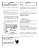
1. Connect the vacuum pump with 250 micron capability to
the service valves.
2. Evacuate the system to 250 microns or less using suction
and liquid service valves. Using both valves is necessary
as some compressors create a mechanical seal separating
the sides of the system.
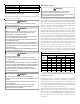
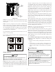
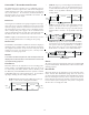
3. Close pump valve and hold vacuum for 10 minutes.
Typically pressure will rise during this period.
• If the pressure rises to 1000 microns or less and remains
steady the system is considered leak-free; proceed to
startup.
• If pressure rises above 1000 microns but holds steady
below 2000 microns, moisture and/or noncondensibles
may be present or the system may have a small leak.
Return to step 2: If the same result is encountered check
for leaks as previously indicated and repair as necessary
then repeat evacuation.
• If pressure rises above 2000 microns, a leak is present.
Check for leaks as previously indicated and repair as
necessary then repeat evacuation.
5000
4500
4000
3500
3000
2500
2000
1500
1000
500
0 1 2 3 4 5 6 7 8 9
10
LEAK(S)
PRESENT
MINUTES
V
ACUUM
IN
MICRONS
CONDENSIBLES OR SMALL
LEAK PRESENT
NO LEAKS
NO CONDENSIBLES
E
LECTRICAL
C
ONNECTIONS
HIGH VOLTAGE!
D
ISCONNECT
ALL
POWER
BEFORE
SERVICING
.
M
ULTIPLE
POWER
SOURCES
MAY
BE
PRESENT
. F
AILURE
TO
DO
SO
MAY
CAUSE
PROPERTY
DAMAGE
,
PERSONAL
INJURY
OR
DEATH
DUE
TO
ELECTRIC
SHOCK
. W
IRING
MUST
CONFORM
WITH
NEC
OR
CEC
AND
ALL
LOCAL
CODES
. U
NDERSIZED
WIRES
COULD
CAUSE
POOR
EQUIPMENT
PERFORMANCE
,
EQUIPMENT
DAMAGE
OR
FIRE
.
WARNING
T
O
AVOID
THE
RISK
OF
FIRE
OR
EQUIPMENT
DAMAGE
,
USE
COPPER
CONDUCTORS
.
WARNING
The condensing unit rating plate lists pertinent electrical data
necessary for proper electrical service and overcurrent protec-
tion. Wires should be sized to limit voltage drop to 2% (max.)
from the main breaker or fuse panel to the condensing unit. Con-
sult the NEC, CEC, and all local codes to determine the correct
wire gauge and length.
Local codes often require a disconnect switch located near the
unit; do not install the switch on the unit. Refer to the installa-
tion instructions supplied with the indoor furnace/air handler
for specific wiring connections and indoor unit configuration.
Likewise, consult the instructions packaged with the thermostat
for mounting and location information.
O
VERCURRENT
P
ROTECTION
The following overcurrent protection devices are approved for
use.
• Time delay fuses
• HACR type circuit breakers
These devices have sufficient time delay to permit the motor-
compressor to start and accelerate its load.
H
IGH
V
OLTAGE
C
ONNECTIONS
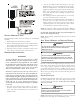
Route power supply and ground wires through the high voltage
port and terminate in accordance with the wiring diagram pro-
vided inside the control panel cover.
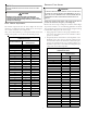
L
OW
V
OLTAGE
C
ONNECTIONS
This heat pump is equipped with a factory-installed transformer
to power the outdoor controls when installed as part of a fully
communicating HVAC system utilizing a ComfortNet™ compat-
ible indoor unit. In this configuration, only two low voltage con-
trol wires are required between the outdoor unit and indoor unit.
The unit also has legacy 24 VAC inputs to support non-commu-
nicating systems. When this configuration is used, the trans-
former in the outdoor unit must be disconnected from the low
voltage and line voltage connections. The transformer connect-
ing wires can then be discarded. Route control wires through
the low voltage port and terminate in accordance with the wir-
ing diagram provided inside the control panel cover.