
GSZC18 Installation

10
COMFORTNET™ SYSTEM ADVANCED FEATURES
The ComfortNet system permits access to additional system in-
formation, advanced setup features, and advanced diagnostic/
troubleshooting features. These advanced features are organized
into a menu structure. See thermostat installation manual for
directions on how to access the ComfortNet User Menus. See
following tables for menu layout.
DIAGNOSTICS
Accessing the air conditioner/heat pump’s diagnostics menu pro-
vides ready access to the last six faults detected by the air condi-
tioner/heat pump. Faults are stored most recent to least recent.
Any consecutively repeated fault is stored a maximum of three
times. Example: The power supply to the air conditioner/heat
pump is continuously below 187 VAC. The control will only store
this fault the first three consecutive times the fault occurs.
NOTE: It is highly recommended that the fault history be cleared
after performing maintenance or servicing the heat pump.
IDENTIFICATION
Model Number, Serial Number and Software Version are displayed
within this menu. A model number check will help determine if
the equipment shared data is correct for the unit. If the model
number is not correct, even though very rare, a memory card is
available to load the proper data.
SENSORS
The outdoor ambient temperature and coil temperature are
displayed in the Sensor Menu. This information can be used
for troubleshooting purposes.
COOL S ET-UP
This menu allows for the adjustment of several cooling perfor-
mance variables. Cool Airflow Trim (range from -10% to 10% in
2% increments), Cool Airflow Profiles, Cool Fan ON Delay, Cool
Fan OFF Delay and Dehumidification Select (enable or disable
dehumidification) can be adjusted in this menu. See the follow-
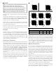
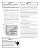
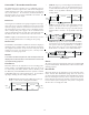
ing images showing the four cooling airflow profiles.
• Profile A (default) provides only an OFF delay of one (1)
minute at 100% of the cooling demand airflow.
OFF
100% CFM 100% CFM
1 min
OFF
• Profile B ramps up to full cooling demand airflow by
first stepping up to 50% of the full demand for 30
seconds. The motor then ramps to 100% of the required
airflow. A one (1) minute OFF delay at 100% of the
cooling airflow.
50% CFM
1/2 min
100% CFM
100% CFM
1 min
OFF
OFF
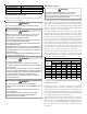
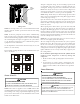
• Profile C ramps up to 82% of the full cooling demand
airflow and operates there for approximately 7 1/2
minutes. The motor then steps up to the full demand
airflow. Profile C also has a one (1) minute 100% OFF
delay.
100% CFM
OFF
OFF
• Profile D ramps up to 50% of the demand for 1/2 minute,
then ramps to 82% of the full cooling demand airflow
and operates there for approximately 7 1/2 minutes.
The motor then steps up to the full demand airflow.
Profile D has a 1/2 minute at 50% airflow OFF delay.
OFF
OFF
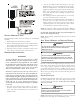
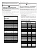
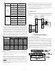
Airflow Tables
STATUS
The current system operational mode and requested indoor CFM
is reported in this menu. This information can be used for trouble-
shooting purposes.
HEAT S ET-UP
This menu allows for the adjustment of several heating perfor-
mance variables. Heat Airflow Trim (range from -10% to 10% in
2% increments), Heat Fan ON Delay, Heat Fan OFF Delay, Defrost
Interval and Compressor Delay can be adjusted in this menu.
Defrost Interval determines the amount of compressor run time
between defrost cycles. Compressor delay selects a compressor
off time after a reversing valve shift.