
Installation Manual


10
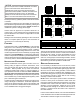
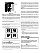
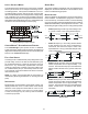
legACy Controls wiring
The intergrated control board on this unit is factory-equipped
with a 4-pin connector for low voltage contols wiring for com-
municating systems. If the system is installed as a non-com-
municating (legacy) system, remove the 4-pin connector and
disconnect the transformer low voltage and line voltage wiring.
Then, install the 7-pin connector that is supplied in the litera-
ture/accessories bag into the intergrated control board in the
appropriate location indicated by the color-coded labels found
on both the control board and pin connector plug.
R C G
O
R C G
O
R C G
O
1 2
System Wiring for legacy controls
ComfortBridge™ system AdvAnCed feAtures
The ComfortBridge system permits access to additional
system information, advanced set-up features, and advanced
diagnostic/troubleshooting features via the control board push
buttons or the CoolCloud mobile app.
fAult Code History
Accessing the air conditioner/heat pump’s diagnostics menu
provides ready access to the last six faults detected by the
air conditioner/heat pump. Faults are stored most recent to
least recent. Any consecutively repeated fault is stored a
maximum of three times. Example: The power supply to the
air conditioner/heat pump is continuously below 187 VAC.
The control will only store this fault the rst three consecutive
times the fault occurs.
NOTE: It is highly recommended that the fault history be
cleared after performing maintenance or servicing the heat
pump.
identifiCAtion
Model Number, Serial Number and Software Version are
displayed within this menu. A model number check will help
determine if the equipment shared data is correct for the
unit. If the model number is not correct or no serial number
is visible, even though very rare, memory cards are available
to load the proper data.
sensor dAtA
The outdoor ambient temperature and coil temperature are
displayed in the Sensor Data Menu. This information can be
used for troubleshooting purposes.
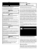
deviCe settings
This menu allows for the adjustment of several cooling perfor-
mance variables. Cool Airow Trim (range from -10% to 10%
in 2% increments), Cool Airow Proles, Cool Fan ON Delay,
Cool Fan OFF Delay and Dehumidication Select (enable or
disable dehumidication) can be adjusted in this menu. See
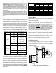
the following images showing the four cooling airow proles.
• Prole A (default) provides only an OFF delay of one
(1) minute at 100% of the cooling demand airow.
OFF
100% CFM 100% CFM
1 min
OFF
• Prole B ramps up to full cooling demand airow
by rst stepping up to 50% of the full demand for
30 seconds. The motor then ramps to 100% of the
required airow. A one (1) minute OFF delay at 100%
of the cooling airow.
50% CFM
1/2 min
100% CFM
100% CFM
1 min
OFF
OFF
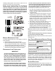
• Prole C ramps up to 82% of the full cooling demand
airow and operates there for approximately 7 1/2
minutes. The motor then steps up to the full demand
airow. Prole C also has a one (1) minute 100% OFF
delay.
100% CFM
OFF
OFF
• Prole D ramps up to 50% of the demand for 1/2
minute, then ramps to 82% of the full cooling demand
airow and operates there for approximately 7 1/2
minutes. The motor then steps up to the full demand
airow. Prole D has a 1/2 minute at 50% airow
OFF delay.
OFF
OFF
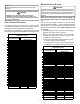
Airow Tables