
Installation Manual


9
The indoor unit, and outdoor unit, comprising of a
ComfortBridge system “communicate” digitally with one
another creating a two-way communications path. The
thermostat still sends commands to the indoor unit, however,
the 24VAC indoor and outdoor unit may also request and
receive information from one another to optimize system
performance.
Two-way digital communications is accomplished using only
two wires between the indoor and outdoor units. The heat
pump control board is powered by 24 VAC, which is supplied
by the factory-installed transformer in the heat pump control
box.
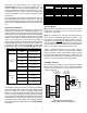
Airflow ConsiderAtion
Airow demands are managed differently in a fully commu-
nicating system than they are in a legacy wired system. The
system operating mode (as determined by the thermostat)
determines which unit calculates the system airow demand.
If the indoor unit is responsible for determining the airow
demand, it calculates the demand and sends it to the ECM
motor. If the outdoor unit or thermostat is responsible for
determining the demand, it calculates the demand and trans-
mits the demand along with a fan request to the indoor unit.
The indoor unit then sends the demand to the ECM motor.
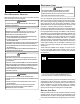
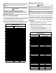
The table below lists the various ComfortBridge compatible
systems, the operating mode, and airow demand source.
System
System Operating
Mode
Airflow
Demand Source
Cooling
Heat Pump
Heat Pump Heating
Only
Heat Pump
HP + Electric Heat
Strips
> of Heat Pump or Air
Handler Demand
Electric Heat Strips
Only
Air Handler
Continuous Fan
Thermostat
Cooling
Heat Pump
Heat Pump Heating
Only
Heat Pump
Auxiliary Heating
Furnace
Continuous Fan
Thermostat
Heat Pump + Air
Handler
Heat Pump +
Furnace
For example, assume the system is a heat pump matched
with an air handler. With a call for low stage cooling, the heat
pump will calculate the system’s low stage cooling airow
demand. The heat pump will then send a fan request along
with the low stage cooling airow demand to the air handler.
Once received, the air handler will send the low stage cooling
airow demand to the ECM motor. The ECM motor then de-
livers the low stage cooling airow. The following table lists
the nominal high and low stage airow for the ComfortBridge
heat pumps.
Hig h
Low Hig h Low
*SZC160241 800 600 800 600
*SZC160361 1200 800 1200 800
*SZC160481 1550 1100 1550 1100
*SZC160601 1800 1210 1800 1210
*SZC180241 850 550 850 550
*SZC180361 1250 850 1250 850
*SZC180481 1550 1210 1550 1210
*SZC180601 1750 1210 1750 1210
Models
Cooling
He at ing
Control wiring
NOTE: Refer to section Electrical Connections - High Voltage
Connections for 208/230 volt line connections to the air
conditioner or heat pump.
NOTE: A removable plug connector is provided with the
control board to make thermostat wire connections. This
plug may be removed, wire connections made to the plug,
and replaced. It is strongly recommended that you do not
connect multiple wires into a single terminal. Wire nuts are
recommended to ensure one wire is used for each terminal.
Failure to do so may result in intermittent operation.
Typical 18 AWG thermostat wire may be used to wire the
system components. However, communications reliability
may be improved by using a high quality, shielded, twisted
pair cable for the data transmission lines. In either case, 150
feet is the maximum length of wire between indoor unit and
outdoor unit, or between indoor unit and thermostat.
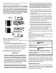
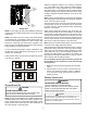
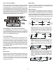
two-wire outdoor
For communicating systems, only two wires are required
between the indoor and outdoor units. This wiring scheme
requires only the data lines, 1 and 2 between indoor and
outdoor equipment.
R
C
G
Y
Optional
Optional
Optional if
feature
supported by
thermostat
INDOOR
BOARD TERMINAL
CONNECTIONS
OUTDOOR
BOARD TERMINAL
CONNECTIONS
OUTDOOR
TRANSFORMER
1
2
C
R
C
G
Y
1
2
C
System Wiring using Two-Wires
between indoor and outdoor equipment